Contrary to your thoughts, it is acceptable. Production cost is actually reduced via this method. Generally speaking (excluding prototype boards), nearly all PCBs are machine cut and drilled. Leaving the PCB in the machine for an additional 10-20 seconds to drill the diode mounting holes cost a few cents. Having an additional machine or person to place them that much more precise is expensive. As you noted these are not reflow mounted. They appear to be mounted using the old fashion belt system where the boards ride on a belt above a molten pool of soldier and air blows small amounts of soldier onto the joint areas. This tech has been in use since at least the 80's when I visited the Motorola factory.
Again, the amount of thermal paste used in this system is less than most others. It is applied with a stencil in a very thin (>1 mil) coating in less then a second as the "heat sink" goes down the line. It's precise, thin, clean, no waste, cost and time effective. Most SMD LEDs cannot have the thermal slugs soldiered and most of the cheaper Chinese LEDs do not have an isolated thermal slug at all. Meaning that if they did soldier it, the entire heat sink then becomes a source for a short in the electronics. You stated the problem with MCPCBs and the thermal transference there, so I won't go over that.
As for more screws, that is not the case at all. They are assembled with preset torque drivers. This makes the pressure across the whole board equal and therefore equal pressure on each slug to the heat sink
.
This is pretty basic electrical engineering stuff. 1oz copper core refers to using a 35 micro meter copper trace route for the circuitry on a PCB. The common sizes are 1, 2, 3 and 5 oz. referring to the weight of the material it would take cover 1 square foot. The resulting thickness after covering that 1 square foot is the thickness measure of the traces. Between each dielectric layer (called the core) an additional layer of thin copper is placed for secondary and tertiary routing.
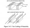
Again, you may want to refresh your basic thermodynamics text. When unducted air is forced over an area of higher temperature, it creates a vortex that rolls the air down over the heated element and back up (to the top of the casing in this instance) then back down again. As the air rolls over the heated surface, transference of heat from the heat sink to the air occurs heating the air and reducing the temperature of the material. This continues to occur until the air finds the path of least resistance to escape, at which time it readily dissipates the heat to the surrounding air. The pull configuration is only marginally better IF the heat sink has fins that the air is forced through.
Reading through the wiki on heat sinks will help you immensely.
![XXO]G81R}U3BE7$[5VQY[~J.jpg](/data/attachments/1734/1734534-b77b64f8153016a1dd903ce9f76a7288.jpg)