DiY LEDs - How to Power Them

NoFucks2Give

Well-Known Member
McCree was the one who measured the action spectrum of the entire leaf
What does that mean "the entire leaf"? He cut a 5mm x 5mm square out of the leaf and used that. He used the existing method used in Balegh and Biddulp at WSU, he even used the same Beckman Co2 analyzer (see attached). He had a very reproducible results due to his process in preparing the specimen before mounting it to the assimilation chamber. He tested a relatively large number of crops. His desire was to work toward a standardization of PAR. He did not coin the term or discover anything regarding wavelength band of PAR. As with most scientific advancements his claim to fame was reproducible results.
 

Attachments

NoFucks2Give

Well-Known Member
Where are your super -efficient designs ,in order for us LED-morons to get a glimpse of awesomeness ?
Took these a few minutes ago of my home lab and a solar powered water cooling test setup in my garage.

June28 001.jpg
June28 002.jpg
June28 003.jpg

And I do green. Taken from my bedroom down the hall to the lab.

WP_20160811_011.jpg

And I do white.

WP_20160813_006.jpg

This is what you CoB Snobs need. 5 amp in and 5 balanced 1 amp out. Zoomed in on the above work bench photo.

lm3466PCB.jpg

Working on another layout and some other things.

Lower left edge is a 8 amp in eight 1 amp out in a more condensed layout.
Upper left corner is a buck constant current regulator 97% efficient. There is only one there now but I will copy that and fill in the edge up to the CCRs. It also has a connector for a thermistor to reduce the current if the LEDs get too hot e.g. the heatsink's water pump fails.
Upper right is some OnSemi CCR circuits e.g NS145090
Lower left edge is to mount Mean Well LDD-H drivers. I will cut them apart to mount some LDD to a some strips of LEDs.
Lower edge is 16 Olsen SSL and Cree XP dual footprint LEDs for use with the on board drivers.
Upper middle an Atmel ATtiny816 with a MAX 202 Serial Port
1 Linear 48-5V regulator
1 switcher 48-5V regulator
I have a dozen Texas Instruments TLC5973 shift register LED RGB drivers. Nine of them driving 24 LEDs. And then a couple more to drive the PWM of the LED Drivers instead of RGB LEDs. One chip gives me 3 PWM circuits for about 10 cents each with an internal shift register to program the 3 duty cycles.

The white unrouted wires are grounds. I will fill the back side with a ground plane then send it off to Advanced Circuits and turn this in to a PCB for $33.

researchPCB.jpg

I do Red White and Blue 16 LEDs of each wavelength on a 12" strip.
The PVC pipe monstrosity is a water tower.

August14 076.jpg

And I do Red. Gap between PCB heat sink and water cooling pipe.

waterCoolingSetupRed.jpg

I saw your 555 LED driver, this is my new driver layout.
The components below the 68µH inductor are the optional thermal control, so the driver could be 0.5" x 0.9"
I have PCBs with 16 and 21 LEDs, 16 for white and blue, and 21 for red so the forward voltages match improving efficiency I'm trying to get the driver to 99% efficiency. When simulated on the TI Web Bench the efficiency is 97% but they build in a higher headroom than necessary. Down the road I want to do a power supply with headroom control so the driver can auto adjust the power supply to match the exact needed voltage for maximum efficiency. Now I have to manually adjust.

lm3466layout.jpg

I also saw your MCPCB. There is no need for an aluminum PCB. There is a much better way to keep and LED cool. With a FR$ they recommend thermal vias. That does not work well. I use thermal vias but just to measure the thermal pad temperature.
 
Last edited:

wietefras

Well-Known Member
What does that mean "the entire leaf"? He cut a 5mm x 5mm square out of the leaf and used that.
He measured the actual leaf itself as opposed to chloroplasts dissolved in liquid.

Those dissolved chloroplast charts are used for schoolkids when they are starting to study the basic chlorophyll process.

That's useless to growers since there is more to plants than just chlorophyl. Growers are interested in how their plants as a whole react to the light. Which is what McCree's charts show most closely.
 

NoFucks2Give

Well-Known Member
He measured the actual leaf itself a
Did you see the 1969 study I posted in my last post. It was the same process that MC Cree used. There were others before him that used the same process. McCree referred to them in his paper both used xenon light source, B&L grating, and Beckman CO2 analyzer.

I'm still trying to make sense out of the McCree study. I wrote an app earlier today where I took the mean data from the 3 tables.

I'm an engineer and programmer not a plant physiologist. It appears at 550nm you are losing at least 50%.
That is if the Absorptance + Action curve is correct. I have my doubts about the +Yield.

McCreeAAY.jpg
 

Attachments

wietefras

Well-Known Member
That's based on the energy weighted McCree charts, but fine.

No need to apply the absorptance. When a photon bounces off it will hit something else. In the end they will all be absorbed somewhere.

What is "+Yield"?
 

stardustsailor

Well-Known Member
Took these a few minutes ago of my home lab and a solar powered water cooling test setup in my garage.

View attachment 3968486
View attachment 3968487
View attachment 3968488

And I do green. Taken from my bedroom down the hall to the lab.

View attachment 3968490

And I do white.

View attachment 3968491

This is what you CoB Snobs need. 5 amp in and 5 balanced 1 amp out. Zoomed in on the above work bench photo.

View attachment 3968492

Working on another layout and some other things.

Lower left edge is a 8 amp in eight 1 amp out in a more condensed layout.
Upper left corner is a buck constant current regulator 97% efficient. There is only one there now but I will copy that and fill in the edge up to the CCRs. It also has a connector for a thermistor to reduce the current if the LEDs get too hot e.g. the heatsink's water pump fails.
Upper right is some OnSemi CCR circuits e.g NS145090
Lower left edge is to mount Mean Well LDD-H drivers. I will cut them apart to mount some LDD to a some strips of LEDs.
Lower edge is 16 Olsen SSL and Cree XP dual footprint LEDs for use with the on board drivers.
Upper middle an Atmel ATtiny816 with a MAX 202 Serial Port
1 Linear 48-5V regulator
1 switcher 48-5V regulator
I have a dozen Texas Instruments TLC5973 shift register LED RGB drivers. Nine of them driving 24 LEDs. And then a couple more to drive the PWM of the LED Drivers instead of RGB LEDs. One chip gives me 3 PWM circuits for about 10 cents each with an internal shift register to program the 3 duty cycles.

The white unrouted wires are grounds. I will fill the back side with a ground plane then send it off to Advanced Circuits and turn this in to a PCB for $33.

View attachment 3968493

I do Red White and Blue 16 LEDs of each wavelength on a 12" strip.
The PVC pipe monstrosity is a water tower.

View attachment 3968495

And I do Red. Gap between PCB heat sink and water cooling pipe.

View attachment 3968496

I saw your 555 LED driver, this is my new driver layout.
The components below the 68µH inductor are the optional thermal control, so the driver could be 0.5" x 0.9"
I have PCBs with 16 and 21 LEDs, 16 for white and blue, and 21 for red so the forward voltages match improving efficiency I'm trying to get the driver to 99% efficiency. When simulated on the TI Web Bench the efficiency is 97% but they build in a higher headroom than necessary. Down the road I want to do a power supply with headroom control so the driver can auto adjust the power supply to match the exact needed voltage for maximum efficiency. Now I have to manually adjust.

View attachment 3968500

I also saw your MCPCB. There is no need for an aluminum PCB. There is a much better way to keep and LED cool. With a FR$ they recommend thermal vias. That does not work well. I use thermal vias but just to measure the thermal pad temperature.
Ok.You got me pretty impressed now.
It seems that you're doing some fine job there.

All is left to do -when you're finished with the device - is to put it in action.
Once again ,electronic engineering -wise ,my opinion is that you are doing a fine job.
But will it back up your claims ?
That is left to be seen .
Keep in mind that in this forum ,there have been quite a few pretty neat LED designs using monos
(search for member " Guod " ) with quite good results -though none was superior than white LEDs.

Also beyond DIY designs ,quite a few LED grow lights of various manufacturers -using various blends of monochromatics- were tested also.None proved to be better than common white LEDs.
On the contrary ,a lot of them -if not most- proved to be quite inferior than white LED grow lights.

So ,should we assume that is not going to be long ,until we 'll witness what your creation can do ?
 

NoFucks2Give

Well-Known Member
What is "+Yield"?
I took the mean values from pages 206, 208, and 210 of McCree, extrapolated the in between wavelengths, and put them in arrays
absorptanceTableMcCree.jpg actionTableMcCree.jpg yieldTableMcCree.jpg


$action = array(350=>9,351=>10,352=>11,353=>11,354=>12, ... 721=>14,722=>13,723=>12,724=>10,725=>9);
$absorptance = array(350=>95,351=>95,352=>95, ...
$yield = array(350=>16,351=>17,352=>18,353=>19,354=>21, ...

Then create the SVG images.
foreach($absorptance as $wavelength=>$value){
$x = (($wavelength - 380) * 2) + 75;
$y = round(300 - ($scale * $value));
echo '<line x1="' . $x . '" y1="300" x2="' . $x . '" y2="' . $y . '" stroke="#3ff" opacity="1"/>' . "\n";
}
The above is for a single array of values in this case absorptance.
Where $absorptance is the array
Wavelength is the array key
Value is the absorptance at that wavelength.

Then I combine the effects of each with others.
Below is the equation for Absorptance+Action+Yield

foreach($yield as $wavelength=>$value){
$y = round(300 - ($scale * $value * ($absorptance [$wavelength] /100) * ($action[$wavelength] /100)));

The equation uses the mean values so if we do 350nm
From the arrays, 350nm:
$action = array(350=>9
$absorptance = array(350=>95
$yield = array(350=>16

Absorptance+Action+Yield = 16 x (95 /100) x (9 /100)

I am not saying Absorptance+Action+Yield is valid. Or any of it is valid. Trying to understand. Just another way to look at it.

If you go here, you can do a View Source and see the SVG image code: http://growlightresearch.com/ppfd/mcCree.php
Fast efficient code.


What I am having a hard time with is the yield fromula:
mcCreeCalculations.jpg
 
Last edited:

NoFucks2Give

Well-Known Member
Where can be found ?
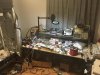
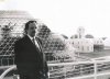
In the horticulture research lab at the University of Florida. Would you like a tour?

But will it back up your claims ?
I saw your MCPCB you do not need metal core.
There is a better way.
How about a 4 foot by 4 foot PCB, with 10,000 µmol at near perfect uniformity across the 4x4 canopy, with a cost under $200?
Yes I know. But we need to have goals.
I have a philosophy where obstacles are all in the mind, and the impossible is only impossible until someone does it.
How about a virtual 4'x4', just cut out what is unnecessary?
How about three 16" PC Boards which end to end is 4 foot.
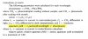
I found the most cost efficient PCB is 10.9" x 16.1". Add 0.1" to either dimension and the cost doubles. I can put 31 16" x 0.35" PCBs on one board with score lines.
0.35" wide and can be populated with 64 LEDs in 4 separate strings of 16, or 3 separate strings of 21. Both 16 blue 2.8V and 21 red 2.1V are around 43-45 Vf.
Will be powered with 48V.
A 48" heat sink with 6 boards attached, three on each side for a total of up to 384 LEDs.
Six of the circuit boards I can make for about $4. For six, $0.67 each.
I can buy 196 LEDs for under $150. Unless I can get another deal like this:
invoiceOlsenSSL80DeepBlue.jpg

Now they need to be cooled. My heat sink is going to cost about $3 a foot in small quantity. So another $12.

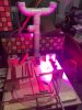
Remember how you said you do not like the Olsen SSL 150? I love them. Why?
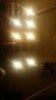
I can run them at inches over the canopy with near perfect uniformity.


Why 196 LEDs
Remember the Cree Horticulture Reference Design, the Gavita 1000W HPS killer? It had 196 LEDs.

So how much power is that?
SSL 150 flux at 350mA is 700mW Radiometric Flux for Blue
Flux at 350mA for Red is 500mW
A 100 each red blue would be 500 umol of photons.
But that means nothing. But that's the math, just the number of photons being emitted from 200 LEDs per second.

The Cree fixture was 400 umol at the canopy from 58 inches with 196 LEDs.
10x inverse square gain from 58" to 12"
So I'm looking at about 4000 umol for under $200.

And I want dimmers, that's another $12 for six of my new Buck Drivers.

I could use white too. (16 streaks from 16 LEDs)

whiteStreaks.jpg

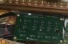
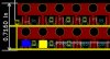
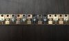
I have a dual footprint design. Accepts Olsen SSL or any Cree XP including the efficient white XP-3G.
The blue square is SSL and the yellow Cree XP
notice how the thermal pad goes up to the heat sink screw hole.

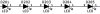
The bottom blue row they are the 2.8v x16 x 4 spaced 6.35mm, the top red 2.1V x 21 x 3 are spaced 6.35mm. notice how the ones on the right is no longer even. 16" down the board they will line up again.

footprint16incher.jpg

My current board is also dual footprint for Luxeon Rebel and Cree XP but wastes space. I love the Rebel Thermal design, it's perfect for my heat sink. But their Color C line is just too small for my eyes and it does not have the Rebel PCB footprint.

Max current is 1 Amp on the SSL 150 so I could boost the output about 2.5x. That would be 10,000 umol under $200.

If I spent another ten cents for the blue I can get 2 Amps. And still be under $200.

And the PCBs are spec'd with HR370 high temp rather then FR4 so I could cut the cost of the board but 6 for $4 is good enough.

With 18 years manufacturing experience, its under control.

Where can you buy them? Not likely going to sell them. Remember the solar test setup.

Do you know there are children that cannot study after school because their village has no electricity?
They have vitamin deficiencies. They need a solar powered vertical farm.
The Cree design was 550 watts. If I have 10,000 µmol I can dim them 10-20x saving electricity where it can easily be solar powered.
I want to give them away. Create a charity organization. Seriously.
Most likely I will make it open source. Put all the mechanical, electrical, and PCB drawings out there free.

Without goals nothing would get done.

Oh yeah, MCPCBs and thermal vias.

Would not a 100% copper path from the LED's thermal pad to the heat sink not be better than putting the heat sink on the opposite side of the board?
I found out that is true.


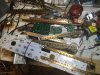
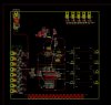
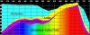
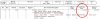
NOW THIS IS THE KEY See how the thermal pad goes to the screw hole?

WP_20160801_003_cr.jpg

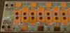
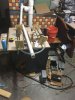
See how the heatsink, the one attached to a copper water pipe, make a 100% copper path from pad to pipe?

copperPipePCB.jpg

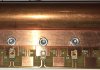
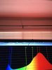
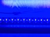
These test results were the first prototype. Remember the red with the gap in my previous post? This is are the results.

waterCoolingResults.jpg

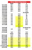
That not bad I have made many improvements since. These results were from a dirty experiment, not a;ll the screws were in, just a shoddy setup.
I found it is important to screw them all down
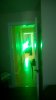
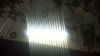
burntLEDs.jpg

And I do blue too.
blue.jpg

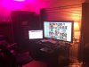
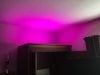
I don't know what you guys have against magenta. This spider on the wall appears to like like it. But everything is not as it appears, see thumbnail.

spiderMagenta.jpg

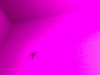
Not as appears, it's on the ceiling not wall. I like magenta enough to use it in my office. I like spiders.

notAsAppears.jpg


None proved to be better than common white LEDs.
Yeah, I think that has to do with thermal management. Red do not like any heat what so ever.

And I can do white if not.

.whiteStreaks.jpg
 
Last edited:

NoFucks2Give

Well-Known Member
So ,should we assume that is not going to be long ,until we 'll witness what your creation can do ?
Soon. Things take time. I started in 1991 with my first grow chamber in Oracle AZ. Four acres under glass. Making progress.


BigGrowChamber.jpg

Actually I wrote their tour booking, hotel reservation, ticket booth, and tour guide scheduling software.

Biosphere II They locked 8 people in an air tight enclosure where the plants had to provide their oxygen and food. It had animals too.

A great experiment. In what though?

NASA was not interested.

It was an experimenter when a crazy rich guy give a bunch of dooms day hippies a quarter of a billion dollars to build a self sustaining environment in preparation for the apocalypse.

Really one of the Bass Bros. that failed in cornering the silver market, gave some hippies living in the NM desert $250,000,000.

How id it work out? They tore it down and built an apartment complex. Nice grow chamber. With a 5 mega-watt generator for the Ac.
 
Last edited:

stardustsailor

Well-Known Member
I
Yeah, I think that has to do with thermal management. Red do not like any heat what so ever.
Everyone has an opinion.
You think that the reds do not cope with heat ,the reason why the blurple light is inferior to white .
Fine by me.
Something tells me that you 're quite willing to try and prove that you're right about this ..

But ...Living tissues are way different than solid state semiconductors
..
:fire:

High DLI of monochromatic "peaky" light( -as opposed to "broad " ),usually with extra power on 660 nm red =>
Too many photons are being ABSORBED by the UPPER chloroplasts inside the leaves of the TOP part of the leaf canopy => Overload of energy => light saturation => Non-photochemical quenching => excess energy from photons is turned into heat and fluorescence in the IR region .

And that's only about red 660 nm ,regarding photosynthesis.
Because too much 660 nm red radiation affects also the phytochrome photoequilibrium
( aka Phytochrome Photostationary State ).
But adding some FR can resolve the latter issue ,quite easily.

Simplified : Where you see "efficiency" ,I see "waste " and visa versa .


Why I 'm under the impression that you did not read the whole paper ?
(...)
When leaves are exposed to greater than saturating light ( energy = power x time =DLI ) ,
the excess light energy absorbed at the top of the leaf must be dissipated as heat.
Heat dissipation at the leaf surface is feasible, and evapotranspiration is a major component of
such dissipation of energy. Any number of possible heat dissipation mechanisms may be involved (Demmig-Adams
& Adams 1992; Sun et al. 1996b). Indirectly, non-plastid absorption by cellular components decreases photosynthetic action (Strain 1950; Inada 1976); and xerophytes tend to have PM that are decreased in diameter, thereby increasing their cell wall per plastid (Shields 1950). The increase in cell wall may afford protection, as cell walls, while being somewhat transparent, also absorb light (see Strain 1950, 1951); they also may aid in transmission of light more deeply into the leaf. Future research aimed at understanding the specific mechanisms that control energy dissipation across the leaf will be enlightening.
The presently evolved absorption characteristics of higher plant Chl’s a and b
allow optimal photosynthesis under saturating and non-saturating light conditions. Under
high photon flux, the blue and red light are efficiently absorbed in the upper part of the leaf.
Since NPQ is linked to light absorbed by Chl and carotenoids, blue and red light absorbed at the top of the leaf must contribute mainly to such quenching when it is induced.


Green light absorbed at the top of the leaf will also be proportionately dissipated.
Thus, light absorbed by Chl and carotenoids at the top of the leaf protects the lower region of the leaf from high photon flux. In particular, the blue light, will be ‘screened’ out and its energy will be dissipated as heat
(see Fig. 7).
In contrast, deep within the leaf where light fluxes are decreased, and there is a strong correlation between the green light gradient and carbon fixation ( no bubbles there for Mr.Engelmann )(Fig. 5c), NPQ will be disengaged; and green light will efficiently drive photosynthesis (Sunet al. 1998 ).

Under low light, however,maximum absorption of blue and red light, when NPQ is
not active, will ensure efficient photosynthesis under non-saturating light conditions (in both the upper and lower region of the leaf)
.

It appears that the particular complement of photosynthetic pigments in higher plants evolved to maximally utilize green light
Sun et a. 1998 ).


Instead of having a maximum extinction in green light, however, higher plant photosynthetic pigments exhibit the lowest extinction in the green. Hence, modulation of green light absorption by leaves and the leaf canopy can occur by varying leaf thickness and the Chl content in leaves, whereas red and blue light absorption varies relatively little (e.g. Rabideau et al.1946; Strain 1951; Moss & Loomis 1952; Inada 1976; seeFig. 7).
( At this point the whole "secret" about green light is revealed ! )

In conclusion, the particular complement of photosynthetic pigments used by higher plants is well suited to the
highly variable light environment on land. Under non-saturating light, maximal utilization of light is possible,
because NPQ is not induced. Under saturating light conditions, when NPQ is engaged, high quantities of blue and red
light energy absorbed in the upper, light-exposed portion of the leaf can be dissipated as heat. Green light trans-
mitted deeply into the leaf, however, can effectively drive photosynthetic electron transport, where NPQ will not be
engaged. If other pigments such as fucoxanthin, biliproteins, or Chl c were utilized by higher plants, the green light
window would be effectively closed, and such dynamic absorption and utilization of light would not be possible.
(..)

http://www.esalq.usp.br/lepse/imgs/conteudo_thumb/Why-are-higher-plants-green--Evolution-of-the-higher-plant-photosynthetic-pigment-complement.pdf

Green light to you -up till now and if I've understood correctly -is "waste".
For me and a bunch of others is the "main fuel " ,since most of us aim
for high PPFD figures ,constantly for 12 long hours .
;-)

Plants due to high absorption can TOLERATE intense blue & red light
either in low light conditions
or in case of high flux only for a relatively short period of time -actually until you notice the change of leaf angle ,meaning just for couple of hours - like mainly during noon ,regarding natural light from the sun .

Example of global (total) irradiance on a horizontal surface for a mostly clear day and a mostly cloudy day in Greenbelt, MD (Thekaekara, 1976): (a) global solar radiation for the day was 27.1 MJ/m2; (b) global solar radiation for the day was 7.3 MJ/m2.
http://www.powerfromthesun.net/Book/chapter02/chapter02.html

Too much of those two light "bands" and the plant turns 'em-quite efficiently - into waste.

But forget all these.
Thing is that most people inside here are not aware of such scientific facts.
But they trust their own eyes.
They 've witnessed in real life ,what the above paper describes .
I think it's your turn-and about time - to experience the same things as other ex-blurple lovers .


Cheers.
:peace:
 
Last edited:

OneHitDone

Well-Known Member
Everyone has an opinion.
You think that the reds do not cope with heat ,the reason why the blurple light is inferior to white .
Fine by me.
Something tells me that you 're quite willing to try and prove that you're right about this ..

But ...Living tissues are way different than solid state semiconductors
..
:fire:

High DLI of monochromatic "peaky" light( -as opposed to "broad " ),usually with extra power on 660 nm red =>
Too many photons are being ABSORBED by the UPPER chloroplasts inside the leaves of the TOP part of the leaf canopy => Overload of energy => light saturation => Non-photochemical quenching => excess energy from photons is turned into heat and fluorescence in the IR region .

And that's only about red 660 nm ,regarding photosynthesis.
Because too much 660 nm red radiation affects also the phytochrome photoequilibrium
( aka Phytochrome Photostationary State ).
But adding some FR can resolve the latter issue ,quite easily.

Simplified : Where you see "efficiency" ,I see "waste " and visa versa .


Why I 'm under the impression that you did not read the whole paper ?
(...)
When leaves are exposed to greater than saturating light ( energy = power x time =DLI ) ,
the excess light energy absorbed at the top of the leaf must be dissipated as heat.
Heat dissipation at the leaf surface is feasible, and evapotranspiration is a major component of
such dissipation of energy. Any number of possible heat dissipation mechanisms may be involved (Demmig-Adams
& Adams 1992; Sun et al. 1996b). Indirectly, non-plastid absorption by cellular components decreases photosynthetic action (Strain 1950; Inada 1976); and xerophytes tend to have PM that are decreased in diameter, thereby increasing their cell wall per plastid (Shields 1950). The increase in cell wall may afford protection, as cell walls, while being somewhat transparent, also absorb light (see Strain 1950, 1951); they also may aid in transmission of light more deeply into the leaf. Future research aimed at understanding the specific mechanisms that control energy dissipation across the leaf will be enlightening.
The presently evolved absorption characteristics of higher plant Chl’s a and b
allow optimal photosynthesis under saturating and non-saturating light conditions. Under
high photon flux, the blue and red light are efficiently absorbed in the upper part of the leaf.
Since NPQ is linked to light absorbed by Chl and carotenoids, blue and red light absorbed at the top of the leaf must contribute mainly to such quenching when it is induced.


Green light absorbed at the top of the leaf will also be proportionately dissipated.
Thus, light absorbed by Chl and carotenoids at the top of the leaf protects the lower region of the leaf from high photon flux. In particular, the blue light, will be ‘screened’ out and its energy will be dissipated as heat
(see Fig. 7).
In contrast, deep within the leaf where light fluxes are decreased, and there is a strong correlation between the green light gradient and carbon fixation ( no bubbles there for Mr.Engelmann )(Fig. 5c), NPQ will be disengaged; and green light will efficiently drive photosynthesis (Sunet al. 1998 ).

Under low light, however,maximum absorption of blue and red light, when NPQ is
not active, will ensure efficient photosynthesis under non-saturating light conditions (in both the upper and lower region of the leaf)
.

It appears that the particular complement of photosynthetic pigments in higher plants evolved to maximally utilize green light
Sun et a. 1998 ).


Instead of having a maximum extinction in green light, however, higher plant photosynthetic pigments exhibit the lowest extinction in the green. Hence, modulation of green light absorption by leaves and the leaf canopy can occur by varying leaf thickness and the Chl content in leaves, whereas red and blue light absorption varies relatively little (e.g. Rabideau et al.1946; Strain 1951; Moss & Loomis 1952; Inada 1976; seeFig. 7).
( At this point the whole "secret" about green light is revealed ! )

In conclusion, the particular complement of photosynthetic pigments used by higher plants is well suited to the
highly variable light environment on land. Under non-saturating light, maximal utilization of light is possible,
because NPQ is not induced. Under saturating light conditions, when NPQ is engaged, high quantities of blue and red
light energy absorbed in the upper, light-exposed portion of the leaf can be dissipated as heat. Green light trans-
mitted deeply into the leaf, however, can effectively drive photosynthetic electron transport, where NPQ will not be
engaged. If other pigments such as fucoxanthin, biliproteins, or Chl c were utilized by higher plants, the green light
window would be effectively closed, and such dynamic absorption and utilization of light would not be possible.
(..)

http://www.esalq.usp.br/lepse/imgs/conteudo_thumb/Why-are-higher-plants-green--Evolution-of-the-higher-plant-photosynthetic-pigment-complement.pdf

Green light to you -up till now and if I've understood correctly -is "waste".
For me and a bunch of others is the "main fuel " ,since most of us aim
for high PPFD figures ,constantly for 12 long hours .
;-)

Plants due to high absorption can TOLERATE intense blue & red light
either in low light conditions
or in case of high flux only for a relatively short period of time -actually until you notice the change of leaf angle ,meaning just for couple of hours - like mainly during noon ,regarding natural light from the sun .

Example of global (total) irradiance on a horizontal surface for a mostly clear day and a mostly cloudy day in Greenbelt, MD (Thekaekara, 1976): (a) global solar radiation for the day was 27.1 MJ/m2; (b) global solar radiation for the day was 7.3 MJ/m2.
http://www.powerfromthesun.net/Book/chapter02/chapter02.html

Too much of those two light "bands" and the plant turns 'em-quite efficiently - into waste.

But forget all these.
Thing is that most people inside here are not aware of such scientific facts.
But they trust their own eyes.
They 've witnessed in real life ,what the above paper describes .
I think it's your turn-and about time - to experience the same things as other ex-blurple lovers .


Cheers.
:peace:
Great information as always @stardustsailor :clap:

Which led's would you see as fitting the bill on spectrum at this current time?
Wish you would revive your amino acid post. Lots of great info in there as well
 

NoFucks2Give

Well-Known Member
I think it's your turn-and about time
One thing I know for sure. When it comes to wavelength recipes, what applies to one spices likely will not apply to another.

I keep an open mind. I also hear from those that are very satisfied with Blue Red. In general I have found the satisfied with Blue Red have higher end fixtures, the dissatisfied had Mars or similar.

I have been on the Red White and Blue bandwagon for some time. I have no issues with using white LEDs. I would not want to use green.
White comes in many flavors. I lean toward the Luxeon Fresh Focus Red Meat and Vero Decor 1750K 97 CRI.

I need to try and keep focused on getting my project completed. Then I can run my own experiments.

I use Red Meat in a lamp in my office along with the spider magenta.

I like that pink glow. Very similar to the Vero Decor.

redMeatReflection.jpg

growLightingOffice.jpg
 

Growcob5

Active Member
Hey buddy hope you don't mind me replying on your thread on a lot of people consider this spam that's like hell are you post to find out any information without replying 5. Chips 34 volt. I want a H LG240 1050mah driver 233volts trying to stretch days 5 times at 5 she and I'm having trouble powering the this cop would you suggest using thicker gauge then 18 gauge non solid core and upgrading it to 24 gauge towards the end pleezz help. IMG-20170629-WA0007.jpeg i need that 5th cob lite lol dam one drive on 3 cobs and other on 5 cobs haveing trubl. Poering 5 4 ok not 5
 

Attachments

Growcob5

Active Member
If you have any ideas on why I'm having trouble please let me know thank you for your time and please forgive me for replying on your thread
 

CobKits

Well-Known Member
-24 ga is not an "upgrade" of 18 ga in fact its smaller

-anything over 18 ga is unnecessary and out of spec for most holders. 18GA is fine and can carry 7A in free air or 3-5A in a cable assembly. 22GA is the absolute smallest you should use in a build and id only use that for 1A or less. no reason not to use 18 solid as its cheap and commonly available

-if one of your cobs isnt lighting its either a bad chip or bad wiring. if theyre in series, it wouldnt be the last one not lighting up, all of them would have issues if you were short on voltage

-take the time to build an aluminum rack, that wooden rack is both an electrical and a fire hazard and has no place in a grow room.
 
Last edited:

NoFucks2Give

Well-Known Member
i need that 5th cob lite lol dam one drive on 3 cobs and other on 5 cobs haveing trubl. Poering 5 4 ok not 5
I have no idea what this is supposed to mean.

g to stretch days 5 times at 5 she and I'm having trouble powering the this cop
Or this

And we are supposed to magically know how you wired this?
They should be wired like this
Untitled.jpg

I'm going to assume you have 5 CoBs being driven by a HLG240-1050 in series.
If you remove a wire from the unlit CoB, do the others go out?
--If the others go out, then either
----1. the wires are reversed or
----2. the CoB is defective.
--If the others do not go out
----you have them wired wrong.

What is the DC voltage across the terminals of the CoB that is not lit up?
 
Last edited:
Top