Scotch089
Well-Known Member
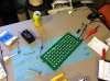
As some may know I have upgraded to the 2012 A51 panels for a while, but I am already itching for more, Guod had helped me out beyond belief and planned out a great sup panel design- though I am not quite ready to order parts for these. In the mean time I figured that I would tinker around on my old panels, instead of selling them, and learning a little more about these panels with some hands on experience.
So far.... what I would like to see happen, would be seperate each heatsink into halve- creating four sup panels, one driver to each- 2 flower, 2 veg dominant. ie WW+R (with nw's+b's for balance?) and NW/CW+B's (with ww+r to balance)
Things are tricky, and since I dont know the draw, brand, bin, yada yada of all of these- im in the dark. Along with the drivers having no info- I need to keep everything on the original drivers. That being said
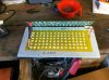
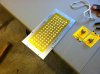
Panel #1
-Channel 1
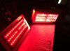
x45 Red emitters
-Channel 2
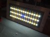
x20 WW
x24 NW
x1 Blue
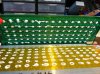
Panel #2
-Channel 1
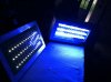
x33 Blue emitters
x12 NW
-Channel 2
x2 NW
x4 WW
x36 Red
x3 'Unknown' ("UV+IR")
All of these are on their respective driver
My intial questions are...
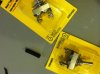
1.) What size wire will I need to use to connect these emitters once they are free from the pcb?
2.) Is adding/mixing/replacing/swapping/removing diodes from each driver a feasible thought?
3.) What kind of compound/epoxy/adhesive do I need to use to keep these on the heatsink and mounted? (I just recently learned that thermal paste stays soft... doh)
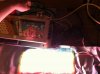
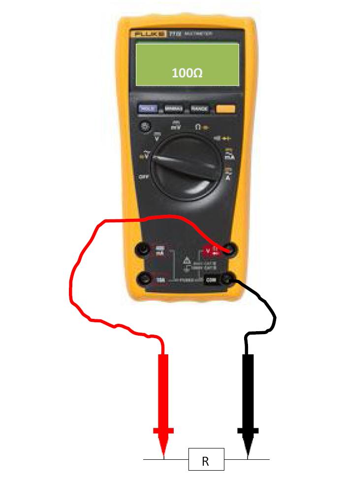
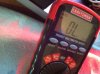
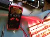
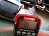
4.) Am I able to determine what the amps/volts/watts of each emitter is by getting a reading off the solder points? Will this tell me what I can and cannot mix and match?
5.) Could I mount these on Star PCB's? if necessary
My goals:
1.) Create a blue supplement for my Flower cab for the first couple of weeks- I play on the led engine and 2 blues added to my 10:2:3 ratio would give me what I am looking for, thought about star pcb's for these?
2.) Couple flower panels out of all the reds
3.) one/couple veg panels with the remainder
I just wanted to hear what others could forewarn me of, maybe things I am overlooking, or over thinking. Hell, I am curious how YOU would do it.
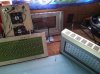
Ill post pics in a second, cheers every one!
So far.... what I would like to see happen, would be seperate each heatsink into halve- creating four sup panels, one driver to each- 2 flower, 2 veg dominant. ie WW+R (with nw's+b's for balance?) and NW/CW+B's (with ww+r to balance)
Things are tricky, and since I dont know the draw, brand, bin, yada yada of all of these- im in the dark. Along with the drivers having no info- I need to keep everything on the original drivers. That being said
Panel #1
-Channel 1
x45 Red emitters
-Channel 2
x20 WW
x24 NW
x1 Blue
Panel #2
-Channel 1
x33 Blue emitters
x12 NW
-Channel 2
x2 NW
x4 WW
x36 Red
x3 'Unknown' ("UV+IR")
All of these are on their respective driver
My intial questions are...
1.) What size wire will I need to use to connect these emitters once they are free from the pcb?
2.) Is adding/mixing/replacing/swapping/removing diodes from each driver a feasible thought?
3.) What kind of compound/epoxy/adhesive do I need to use to keep these on the heatsink and mounted? (I just recently learned that thermal paste stays soft... doh)
4.) Am I able to determine what the amps/volts/watts of each emitter is by getting a reading off the solder points? Will this tell me what I can and cannot mix and match?
5.) Could I mount these on Star PCB's? if necessary
My goals:
1.) Create a blue supplement for my Flower cab for the first couple of weeks- I play on the led engine and 2 blues added to my 10:2:3 ratio would give me what I am looking for, thought about star pcb's for these?
2.) Couple flower panels out of all the reds
3.) one/couple veg panels with the remainder
I just wanted to hear what others could forewarn me of, maybe things I am overlooking, or over thinking. Hell, I am curious how YOU would do it.
Ill post pics in a second, cheers every one!


 .
.