EFs R&DiY LED, Circuits, Arduino, Hot Peppers and more thread

epicfail

Well-Known Member
So I was thinking I should start a thread here to keep some of my projects and ideas, More for me than anyone else but feel free to follow along. I am learning this electronics stuff and am by no means an expert but I will post what I figure out when I figure it out in case it helps others.

I am currently working on a Cree CXA3070 project and am just awaiting for some final parts to arrive to finish it off. I will post more about that when I start building, there will be pics.

I like to do things my way which is usually not the easiest or smartest way and most definitely not the cheapest. Part of the project requires 140mm 12v PC fans to actively cool the heatsinks. The fan speed is usually controlled by varying the voltage load to the fan, lower voltage equals lower speed. This way works but I want to use the NOCTUA NF-A14 industrialPPC-3000 PWM fans and already have a 60w 12v power supply laying around. My original plan was to try and control them with a signal from the arduino to the 4th wire on the fan. Well it seems that 4-wire fans require a high frequency (25Khz) and though the arduino is capable of doing this it, I found I could not get more than 1 channel to work and I needed 2. There might be away but I haven't found it yet, what I did find was this circuit on an overclockers forum (thanks to those guys).

okzwd4.png
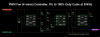
I know there are other circuits that use a 556 but locally I could get all the parts for this circuit. My plan is to maybe later if I learn how, replace that 10K Ω pot with a 8 bit digital pot controlled from the arduino. I bought 4 of those fans they are IP52 rated($31cdn each) and then I bought one of the of their NF-A14 industrialPPC-2000 IP67 PWM ($35). I have no use for it but when I saw this video I had to get it.


Like always I am probably over thinking this and definitely over engineering this but that is just who I am.

More to come...
 
Last edited:

guod

Well-Known Member
from an other disaster thread...
controlling 2 fans
in red the new code
blue: my comments


const int analogInPin = A0; // Analog input pin that the potentiometer is attached to

const int FanControlPin_a = 3; // Digital pin that the PWM fan is attached to
// we need a second control pin

const int FanControlPin_b = 11; // Digital pin that the PWM fan is attached to
// pin 3 or 11 for 25khz frequency for pc fans

int PotValue = 0; // value read from the pot
int outputValue = 0; // value output to the PWM (analog out)


void setup() {
// initialize serial communications at 9600 bps:
Serial.begin(9600);

// this is to change the pwm frequency of pin 3 to around 25khz for PC FANS
pinMode(3, OUTPUT);
pinMode(11, OUTPUT);
TCCR2A = _BV(COM2A0) | _BV(COM2B1) | _BV(WGM21) | _BV(WGM20);
TCCR2B = _BV(WGM22) | _BV(CS21);
OCR2A = 79;
OCR2B = 39;
}


void loop() {
// read the analog in value:
PotValue = analogRead(analogInPin);
// map it to the range of the analog out:
outputValue_a = map(PotValue, 0, 1023, 24, 79); // change value of fan speed
// from 0-255 to 24-79 (0-100%)
// generate a value for the second port

outputValue_b = map(PotValue, 0, 1023, 24, 39); // change value of fan speed
// from 0-255 to 24-39 (0-100%)

// change the analog out value:
analogWrite(FanControlPin_a, outputValue_a);
// second value out

analogWrite(FanControlPin_b, outputValue_b);

// print the results to the serial monitor:
Serial.print("sensor = " );
Serial.print(PotValue);
Serial.print("\t output = ");
Serial.println(outputValue_a);
Serial.println(outputValue_b);


// wait 2 milliseconds before the next loop
// for the analog-to-digital converter to settle
// after the last reading:

delay(2);
}
 

epicfail

Well-Known Member
@goud, thanks for the code but it has problems. I changed

int outputValue = 0;

to

int outputValue_a = 0;
int outputValue_b = 0;


then it compiles fine but I actually cant control either fan with the pot. Fan_a on pin 3 gets 100% duty cycle and fan_b on pin 11 gets 0%. When I turn the pot nothing happens to fan speed but output in the serial monitor is correct.

If I remove the line

analogWrite(FanControlPin_b, outputValue_b);

then the pot works to control fan_a but if paste it back and remove this line instead

analogWrite(FanControlPin_a, outputValue_a);

fan_b still does nothing. This get me back to where I started. I think is has something to do with changing the frequency of timer 2 (pins 3 and 11), I don't really understand the timer stuff to well (or at all). I believe when changing the frequency you are tricking the timer but shortening the amount of steps it take up and down (I hope this make sense). Instead of the timer doing going from 0-255 to complete its cycle the line

OCR2A = 79;

sets the TOP to 79 shorting the cycle from 256 steps to 80 making each cycle faster thus increasing the frequency. In doing this I think I lose PWM control though should be able to generate a fix duty cycle of 50% on pin 11 but also at half frequency and the fan will not operate at those specs. I could be misunderstanding this.


Varying the timer top limit: fast PWM

Both fast PWM and phase correct PWM have an additional mode that gives control over the output frequency. In this mode, the timer counts from 0 to OCRA (the value of output compare register A), rather than from 0 to 255. This gives much more control over the output frequency than the previous modes. (For even more frequency control, use the 16-bit Timer 1.)

Note that in this mode, only output B can be used for PWM; OCRA cannot be used both as the top value and the PWM compare value. However, there is a special-case mode "Toggle OCnA on Compare Match" that will toggle output A at the end of each cycle, generating a fixed 50% duty cycle and half frequency in this case. The examples will use this mode.

In the following diagram, the timer resets when it matches OCRnA, yielding a faster output frequency for OCnB than in the previous diagrams. Note how OCnA toggles once for each timer reset.

http://arduino.cc/en/Tutorial/SecretsOfArduinoPWM


Once again though, I'm just learning and appreciate the help.
 
Last edited:

guod

Well-Known Member
read your code a bit deeper...

-------------------------------------------------------------------------------------

const int analogInPin = A0; // Analog input pin that the potentiometer is attached to

const int FanControlPin = 3; // Digital pin that the PWM fan is attached to

// pin 3 for 25khz frequency for pc fans

int PotValue = 0; // value read from the pot
int outputValue = 0; // value output to the PWM (analog out)


void setup() {
// initialize serial communications at 9600 bps:
Serial.begin(9600);

// this is to change the pwm frequency of pin 3 to around 25khz for PC FANS
pinMode(3, OUTPUT);
TCCR2A = _BV(COM2A0) | _BV(COM2B1) | _BV(WGM21) | _BV(WGM20);
** COM2A0 - Toggle OCDA on Compare Match
** COM2B1 - Clear OCDB on Compare Match
** WGM21 & WGM20 - Fast PWM Mode (3/7) Wraps around at 0xFF (3) or OCR2A (7)


TCCR2B = _BV(WGM22) | _BV(CS21);
** WGM22 count to OCR2A instead to 255 - Mode (7)
** CS21 Prescaler = 8 >> 78.125kHz


OCR2A = 79;
** next Prescaler to get 25kHz see WGM22


OCR2B = 39;
value for dutycycle on pin 3 - Mode (7)
}


void loop() {
// read the analog in value:
PotValue = analogRead(analogInPin);
// map it to the range of the analog out:
outputValue = map(PotValue, 0, 1023, 24, 79); // change value of fan speed


// change the analog out value:
analogWrite(FanControlPin, outputValue);
this is the standart PWM-Mode;
i think, all settings above are gone except the setting for the CS21 Prescaler.


"After a call to analogWrite(), the pin will generate a steady square wave of the specified duty cycle until the next call to analogWrite"

see http://arduino.cc/en/pmwiki.php?n=Reference/AnalogWrite

your fan is now controlled by a 31.25kHz PWM Signal.
fan seems to work on higher freq.


runnig the fan on 25kHz PWM we have set the OCR2B register
OCR2B = outputValue
Output B duty cycle: (outputValue+1) / (79+1)

-------------------------------------------------------------------------------------

if the fans really working above 28kHz(see spec.) than 2 fans will be easy...

if not... using the 16bit Timer maybe

http://courses.cs.washington.edu/courses/csep567/10wi/lectures/Lecture7.pdf
http://courses.cs.washington.edu/courses/csep567/10wi/lectures/Lecture6.pdf
 

epicfail

Well-Known Member
My ghost peppers were barely hanging on to life, I thought it was the soil,it was a Coco and Seasoil mix. I figured there was to much salts from not rinsing the coco enough so I changed them to some store bought mix. Out of 13 I have two left outside which are still struggling and one I moved to DWC indoors under some XML2s, it is starting to take off...
Well I took this picture on july 27th after the plant had recovered from being outside in soil then transferred to indoor DWC with 20 watts of LED.

Ghost_Pepper_DWC.jpg
It has been 11 days since then and the thing is doing great, I topped and trained it to stay low so I can keep it close to the XML2's. It is a complete turn around to its life outside the others I have out there are still suffering. I wasn't sure if it was going to the flower indoors but today I found some buds so it looks like its might.

gp0.JPG
gp1.JPG gp2.JPG
 
Last edited:

epicfail

Well-Known Member
Look what arrived today :hump:


Black_HS1.JPG Black_HS2.JPG
That's six feet of the 5.886" profile from heatsinkUSA. I lapped it to 1000 Grit US and sent them out to have them anodized black. $90 for the anodizing, worth it in my opinion. After around 12 hours of lapping I wanted to protect the surface from scratches and the black helps with thermal dissipation. These will be good for years.
 

epicfail

Well-Known Member
Well I stuck wet/dry sandpaper to a glass piece I use as a sanding block, took my time and go thru the grits. I was only sanding in one direction (no back and forth) and then switching directions ninety degrees with each grit. I realize that the whole surface will not be perfectly flat as a whole but each individual square inch should be pretty damn close to perfect. Since the LEDs are only about an inch or so big there should be pretty even contact, The heatsinks come as raw aluminum extruded like spaghetti so even sanding them with 100 Grit on a palm sander would be a major improvement, I went to 1000g because I believe that is what cree is recommending.

At one point I was sanding one of the heatsinks and it got dry, and a piece of aluminum built up and gouged the heatsink (must have been stoned). I had to start over with a rougher grit and remove the gouge, thats when I decided to get the anodizing done. I was putting in so much labour for something that was just going to oxidize and scratch, I figured I can use these heatsinks over and over again. This will protect them and increase their performance, plus it makes them look cooler.
 

epicfail

Well-Known Member
I don't think I'm going to drill them, at least not at first. I can solder the CXA's and kapton tape them on like @SupraSPL has done with his and the others he has made. These heatsinks were designed for actively cooling around 150 watts with a standard 1000rpm 140mm pc fan, I went overboard and got the 3000 rpm industrial pwm fans. I will just dial them down but can turn them up if needed. I am probably only going to run like 60 watts of led on each of them at first but they were made to be upgraded and added too. All 4 heatsinks will be put in a 2x4 gorilla tent for now (too much?) but when there is more space in the future they will be ready to handle it.
 

epicfail

Well-Known Member
Really if I had the money and they were available I would be adding some top bin 2700K, 2 per heat sink. It would then have 2x 3000k 2x 2700k in series run off a HLG-185H-C1050B. I would just dial them down to 60% or so for better efficiency and spread, but could crank them up if I get more space. Thats when the high RPM fans will come in handy, maybe by the time cree releases an AB bin 2700k I will be ready to add.

I guess I could just add single 3590 2700K BB if I can find those instead of 2x 3070, No rush though.
 

salmonetin

Well-Known Member
:bigjoint:crazy idea?...
an tube for heatsink/s in a similar way than an cooltube way only to remove the hot air on heatsink out of indoor...

:confused:

saludos
 
Last edited:
Top