GrowLightResearch
Well-Known Member
And a very good grower at that. And I'm not blowing smoke.better performance with series hookup??
please try to make it easy to understand..because i am not a tech..i am a grower
I am very good at tech and so so with plant physiology, but I know people that know a lot.
When the Vf does not match exactly, you are putting stress on them and the run slightly less efficient but not enough to matter much, a few dollars a year in electricity. Their further apart the Vf the more stress and inefficiencies.
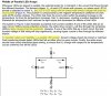
Because I have seen too many strips and CoBs significantly unbalanced. See my previous post in this thread.you are saying that parallel is not as good because??
I look for opportunity where there are problems and then create a solution to the problem.
To find problems I have to look hard and understand every detail of a system. I have been researching horticulture grow lighting for a few years now. I used to think LEDs were simple.
Why did you not solder in a new LED?The boards works great, resistance is almost identical, as the solder worked to create adequate resistance to rebalance the circuit again
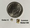
I would suspect those Color C LEDs will likely have issues if wired in parallel. The get too hot and if their Vf is anything like Rebel, matching strips Vf would be too problematic. Logistically an inexpensive buck step down driver with thermal overload protection would be easier, more efficient, in the long run cheaper, and much more reliable. Parts cost and the parts count to build a driver keeps going down. I found some very small inexpensive Coilcraft inductors that are perfect for a 1 amp driver. Coilcraft knows how to make inductors. I've been using them for over 30 years.I have been using Lumileds Luxeron SunPlus 20 diodes for the reds and blues.
this is a thumbnail, actual size is over1600px. That's just too damn small. For my eyes.
I used to think LEDs were that simple too. LEDs have a dynamic resistance. More dynamic that most will ever understand.after all a diode is resistor,
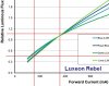
The resistance is characterized in the datasheet's IV curve. Datasheets use typical values but there is NOTHING typical about an LED. The IV curve and the fact that every LED's IV curve is different is why you do not want to wire them in parallel. Especially when their heat is generated and concentrated in a tiny little package. The Color C / SunPlus 20s were targeted for entertainment spot lights which need a lot of flux in a small spot. I think they get too hot to place close to one another on a PCB. So the "bigger", if you can call 2.5mm bigger, should work better than the aging Color C Line. Today I like OSRAM for horticulture.
Too many think an LED is like a light bulb. An LED is NOTHING like a light bulb. I also find becasue people tend to view LEDs as a light bulb they make poor decisions when put them to use. I do not think LEDs should be used in light bulb. Light bulbs are from Edison's time. Lighting needs to be looked at from a new out of the box perspective.
I think stuffing a bunch of high powered LEDs into a high bay fixture is stupid as stupid gets. An LED high bay is now an expensive heatsink with LEDs mounted to the heatsink. Same for light bulbs. The heat is not good for LEDs. 50,000 hrs? Bullshit.
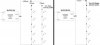
LEDs need to be spread out to ease the thermal management. Many find that to be to costly becasue they think it would require a big expensive MCPCB. For example if we were to replace high bay fixtures by spreading individual LEDs across the entire ceiling with that line of though it would require a PCB the size of the ceiling. So what do they do? They compromise. They make a bigger PCB than a light bulb but not too big. So they end up with a 1 sq. ft. PCB which drives up the price. My choice is to make a strip only big enough to solder on the LEDs and mount the strip to a heatsink. My new strips are 0.25" or 9mm wide. The least expensive PCB panel size is 16" x 20" on which I can fit almost 60 16" long strips. The panel is laid out with 50 strips with four strings of 16 Nitride LEDs and ten strips with three strings of 21 Gallium LEDs. 16 inch works well because three of them will make a 48" strip which seems to be popular length. But yet has flexibility to fit anywhere. If I were to populate every LED I could make a 48" strip with enough flux to equal a 1000W HPS.
I'm doing the strings of 21 gallium as an experiment. I want to experiment with yellow. Yellow is know to mitigate elongation when yellow is used with seedlings. I also have a sneaky suspicion that yellow is the reason HPS does so well.
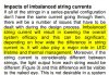
In the excerpt from a graduate level plant physiology textbook I highlighted one sentence. This is why I want to try the blue and yellow with seedlings.
There are several ways to experimentally separate a reduction in elongation rates mediated by phytochrome from a reduction mediated by a specific blue-light response. If lettuce seedlings are given low fluence rates of blue light under a strong background of yellow light, their hypocotyl elongation rate is reduced by more than 50%. The back-ground yellow light establishes a well-defined Pr-fr ratio (see Chapter 17). In such conditions, the low fluence rates of blue light added are too small to significantly change this ratio, ruling out a phytochrome effect on the reduction in elongation rate observed upon the addition of blue light.
Blue light and phytochrome-mediated hypocotyl responses can also be distinguished by the swiftness of the response. Whereas phytochrome-mediated changes in elongation rates can be detected within 8 to 90 minutes, depending on the species, blue-light responses are rapid, and can be measured within 15 to 30 s (Figure 18.6). Inter-actions between phytochrome and the blue light–dependent sensory transduction cascade in the regulation of elongation rates will be described later in the chapter. Another fast response elicited by blue light is a depolarization of the membrane of hypocotyl cells that precedes the inhibition of growth rate (see Figure 18.6). The membrane depolarization is caused by the activation of anion channels (see Chapter 6), which facilitates the efflux of anions such as chloride. Use of an anion channel blocker prevents the blue light–dependent membrane depolarization and decreases the inhibitory effect of blue light on hypocotyl elongation (Parks et al. 199") .
.
Blue Light Regulates Gene Expression Blue light also regulates the expression of genes involved in several important morphogenetic processes. Some of these light-activated genes have been studied in detail—for example, the genes that code for the enzyme chalcone synthase, which catalyzes the first committed step in flavonoid biosyn-thesis, for the small subunit of rubisco, and for the proteins that bind chlorophylls aand b(see Chap-ters 13, 8, and 7, respectively). Most of the studies on light-activated genes show sensitivity to both blue and red light, as well as red/far-red reversibility, implicating both phytochrome and specific blue-light responses.
Blue light and phytochrome-mediated hypocotyl responses can also be distinguished by the swiftness of the response. Whereas phytochrome-mediated changes in elongation rates can be detected within 8 to 90 minutes, depending on the species, blue-light responses are rapid, and can be measured within 15 to 30 s (Figure 18.6). Inter-actions between phytochrome and the blue light–dependent sensory transduction cascade in the regulation of elongation rates will be described later in the chapter. Another fast response elicited by blue light is a depolarization of the membrane of hypocotyl cells that precedes the inhibition of growth rate (see Figure 18.6). The membrane depolarization is caused by the activation of anion channels (see Chapter 6), which facilitates the efflux of anions such as chloride. Use of an anion channel blocker prevents the blue light–dependent membrane depolarization and decreases the inhibitory effect of blue light on hypocotyl elongation (Parks et al. 199
Blue Light Regulates Gene Expression Blue light also regulates the expression of genes involved in several important morphogenetic processes. Some of these light-activated genes have been studied in detail—for example, the genes that code for the enzyme chalcone synthase, which catalyzes the first committed step in flavonoid biosyn-thesis, for the small subunit of rubisco, and for the proteins that bind chlorophylls aand b(see Chap-ters 13, 8, and 7, respectively). Most of the studies on light-activated genes show sensitivity to both blue and red light, as well as red/far-red reversibility, implicating both phytochrome and specific blue-light responses.
It's about morphogenetic. My hypothesis is thecells affected by the polymorphism will persist for at least six weeks before the cells with the altered gene expression due to the BY lights die. polymorphismis the environmental factor in genetics. Lifeforms need to adapt to their environment. One of the best examples is a tiger's strips. Of course a tiger's strips are a genetic factor. Bu the shape and color is environmential and brought about via polymorphism. I get the six weeks from addiction research. Habitual crack and meth users develop chemically induced psychosis. They found the morphogenetic genes that cause the psychosis and other associated symptoms die off after six week when they stop smoking their drugs.
I do go off on tangents. I am not offended wen people call me crazy. I get that. Back to the topic at hand. Well let me first finish the point to yellow and the gallium strips.
Yellow is the least efficient gallium LED because its band gap is the widest with its wavelength being so far away from red the ideal color for gallium. Wide band gap equates to more energy consumed. And yellow can easily lose 80% of its flux to temperature when it reaches 100°C. Were a nitride blue or white will only lose 10% at 100° C.
I find a 48" strip would be problematic to manufacture. A pick and place robot that can handle a 48" dimension would cost too much for low volume. Samsung does not have that problem. They probably make their strips on slightly outdated mobile phone production lines.
I had a Zevatech 760 which was a great machine in almost new condition. When I move I had some one move it for me. He had it stored in a warehouse. when I contacted him to get it I found out he was dead. He went on a date with a girl from Craigslist and was met by three guys with baseball bats and they robbed him and beat him to death. And I did not know where the warehouse was. He had my entire manufacturing line stencil printer PnP, and convection oven.
Last edited:
 He who laughs lasts laughs longest. Dumb ass!