foreverflyhi
Well-Known Member
Alright so let's do this, I always wanted to do this and truthfully I was inspired by all the people making DiY led panels!
Awhile back, I purchased a light from Cidly, if your not familiar with them google it, pretty much shitty Chinese led panels for a cheaper price.
It's suppose to be a 360 watt 3w diodes.
It did fine for about 4 months then one led at a time went out.
I was going to return it but then I decided to keep it and fuck with it later down the road, well the time is here!
Let's take it apart and put it back together with upraded parts RIU!
I'm going to take it apart and show y'all what's inside,
let's test it,
see what's wrong with it,
Maybe we can salvage some things in it?
And after all that lets order the best of the best diodes for it,
Then when we r done lets grow some dank with it!
If y'all didn't catch my drift I kept saying "let's" meaning I want everyone's help with this(no worries I got the funds) I want all of us to put our input and make this panel legit!
So let's get started with the pics
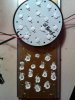
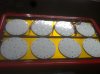
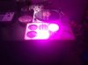
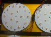
Here's the panel when it's on and off
 <---yes that is a cum stain, i cant help myself with these leds panels!! haha jk...
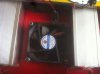
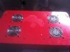
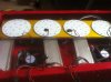
has 4 fans which all work so im geussin that all the power supplies are working

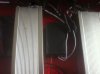
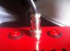
Power switch, one side turns the unit on the other side doesn't do anything, once again shitty led
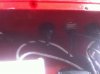
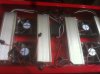
Power supply, looks simple enough for me too understand how it works kinda..


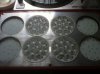
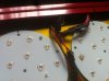
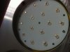
here are the diodes most of them dont work to the best of my knowledge, maybe it can be due to the drivers
but i actually think they got burnt out

ok so now what next yall?
i dont know much about the drivers so i wana get more info on that.
i wana run some test to see what is exactly broken, just not sure where to begin.
lets do some shoping for some bad ass diodes and maybe even drivers?
once agian this is a community project so this may take awhile, at the end this will be worth it,
and because this is a community project i think its only fair we name the remodeled panel, RIU LED
Awhile back, I purchased a light from Cidly, if your not familiar with them google it, pretty much shitty Chinese led panels for a cheaper price.
It's suppose to be a 360 watt 3w diodes.
It did fine for about 4 months then one led at a time went out.
I was going to return it but then I decided to keep it and fuck with it later down the road, well the time is here!
Let's take it apart and put it back together with upraded parts RIU!
I'm going to take it apart and show y'all what's inside,
let's test it,
see what's wrong with it,
Maybe we can salvage some things in it?
And after all that lets order the best of the best diodes for it,
Then when we r done lets grow some dank with it!
If y'all didn't catch my drift I kept saying "let's" meaning I want everyone's help with this(no worries I got the funds) I want all of us to put our input and make this panel legit!
So let's get started with the pics
Here's the panel when it's on and off
<---yes that is a cum stain, i cant help myself with these leds panels!! haha jk...has 4 fans which all work so im geussin that all the power supplies are working
Power switch, one side turns the unit on the other side doesn't do anything, once again shitty led
Power supply, looks simple enough for me too understand how it works kinda..
here are the diodes most of them dont work to the best of my knowledge, maybe it can be due to the drivers
but i actually think they got burnt out
ok so now what next yall?
i dont know much about the drivers so i wana get more info on that.
i wana run some test to see what is exactly broken, just not sure where to begin.
lets do some shoping for some bad ass diodes and maybe even drivers?
once agian this is a community project so this may take awhile, at the end this will be worth it,
and because this is a community project i think its only fair we name the remodeled panel, RIU LED