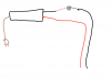
He's at 120VDC & 2A max (240W, and LED boards aren't inductive loads, though that doesn't completely rule out the possibility of inductive arching, yet) while smallest test in vid was 250VDC 3.5A (875W; and decently inductive load, notice no spark on close event despite having 250VDC, 2× what OP has, while large arc on open event = inductive circuit). And yes, ideally you'd want to switch the AC side but OP wants switches in his tent (DC side).
ALL mechanical switches regulating load power (inductive circuits) will have an arc upon human powered open event, just the nature of the beast. The greater the circuit's inductance (over capacitance) the greater the arc event. I'd assume he may have to replace a switch or 2 every 3-4 years or so, but they don't look spendy, thats why I think they'd work "fine."
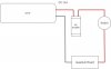
Alternatively one could add an RC snubber in parallel to the switch (which is commonly implemented when dealing with inductive voltage spikes) and then you'd not have to worry about arc, though just adding a solid state switch will not get rid of inductive voltage spikes (which can damage MOSFET's) and the solid state route also needs low voltage power to control it and/or add other components/circuits.
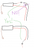
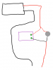
@Hot Diggity Sog, if you notice arc and want to arrest it, add an RC snubber in parallel with the switch. Try a 0.1μF film cap (rated 400V or more) and maybe 60-120Ω R underneath it. The component values are (also) influenced by the circuit inductance which we don't know atm, so these are just ballpark guesses. I don't foresee any big issues if you don't use a snubber but if you do notice some arcing and want your switches to last longer,
@Sinfor is right, you'd want a snubber. LEDs are typically thought of as capacitive loads but there may be inductance before the switch (in the driver) that may want to cause arcing at open event (turn OFF). It's pretty easy just to wack one in there, otherwise I'd just repair as needed. Also can look at MOV's.
*
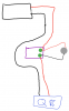
Could add 100k-1MΩ R across snub cap to eliminate high snub cap voltage (could cause possible arc) at switch close event (turn ON).
**
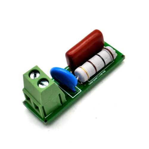
Here you go, $1.50, this one comes with a MOV too:
Find many great new & used options and get the best deals for RC Snubber Module Relay Contact Protection Circuit Electromagnetic at the best online prices at eBay! Free shipping for many products!
www.ebay.com