New style Samsung LM561C Board

conversekidz

Well-Known Member
I'm not saying that it could not have been avoided with better practice. It is difficult to judge the line between boards being tight to ensure good contact with heat-sink and over tightening. Also even at a moderate tightening , if during the tightening process the screw rotates it can easily rupture the silkscreen. It also seems softer then most other pcb's I have dealt with.

In regards to isolation media I had no idea there was copper under the mounting holes as I assumed it is a simple and standard practice that there would not be any

Are you saying that there should be copper around the mounting holes ?
1: If you use a thermal paste you would not have needed to tighten it as much to make sure you have contact between your board and your heat sink...Unless you are surface polishing your heat sink via granite and the same goes for your light panel, you will have poor thermal transfer.

2: Why are you tightening a screw direct against silk screen...you should not be using the silk screen as your only isolation barrier, poor practices on your part does not denote a design flaw.

3: Did you spec the aluminum for the board? If not, not a design flaw.

4: You should have inspected the board prior mounting or energizing it. Looking at the board you can see where the traces are located.

5: Building on #3...Did you spec the board, did you design it? If not, neither you or I know if there should or should not be copper at the location on the board.

Assumptions are what get people killed <3
 

DankaDank

Well-Known Member
1: If you use a thermal paste you would not have needed to tighten it as much to make sure you have contact between your board and your heat sink...Unless you are surface polishing your heat sink via granite and the same goes for your light panel, you will have poor thermal transfer.
I'm pretty sure there is very few people mounting large PCB's with thermal compound. That is one of the main advantages of having a large metal core surface area. Even so if thermal is applied it is recommended to re-tighten after the light has been run a few times.
2: Why are you tightening a screw direct against silk screen...you should not be using the silk screen as your only isolation barrier, poor practices on your part does not denote a design flaw.
Well as I have already pointed out the silkscreen around the mounting holes should not be insulating anything.
3: Did you spec the aluminum for the board? If not, not a design flaw.
Unfortunately I'm not following you on this one, could you kindly elaborate.
4: You should have inspected the board prior mounting or energizing it. Looking at the board you can see where the traces are located.
You are absolutely correct, I should have inspected the copper layout of the PCB prior to mounting it like I'm sure most people do. This is my mistake and why I posted about it to potentially help people from making such a silly mistake.
5: Building on #3...Did you spec the board, did you design it? If not, neither you or I know if there should or should not be copper at the location on the board.
Well I did not design it but if i did there would certainty not be live copper around the mounting holes. But after investigating the copper layout when I found the fault there is a absolutely no reason why there should be live copper around the mounting holes.

Assumptions are what get people killed <3
This is why I thought I better just let people know about my assumption. This way I can save lives and avoid people potentially killing them selves if they where to potentially make the same silly mistake. But if manufactures just had some basic safety practices it would be better don't you think?
 

nfhiggs

Well-Known Member
1: If you use a thermal paste you would not have needed to tighten it as much to make sure you have contact between your board and your heat sink...Unless you are surface polishing your heat sink via granite and the same goes for your light panel, you will have poor thermal transfer.

2: Why are you tightening a screw direct against silk screen...you should not be using the silk screen as your only isolation barrier, poor practices on your part does not denote a design flaw.

3: Did you spec the aluminum for the board? If not, not a design flaw.

4: You should have inspected the board prior mounting or energizing it. Looking at the board you can see where the traces are located.

5: Building on #3...Did you spec the board, did you design it? If not, neither you or I know if there should or should not be copper at the location on the board.

Assumptions are what get people killed <3
I worked for a company that made circuit boards for medical diagnostic equipment - mind you, this was a 2-3 billion dollar per year company, not some small outfit. I worked in the test/quality department. One of the large backplane boards had 49 pin D-sub connectors that were soldered to the board, but also had screws at each end of the connector, that went through the connector and the board with nuts on the bottom (board) side. Every time they had a new assembler putting these particular boards together we would start seeing shorts from the floating ground plane to the chassis ground when testing them. The build plan called for a lock washer (split type washer) and a flat washer under the nut on the bottom side. Invariably the new person would randomly swap the positions of the lock washer and the flat washer, placing the lock washer against the board surface instead of the flat washer. The lock washer would cut through the solder mask and into the top copper layer when it was tightened down, shorting that layer (the floating ground) to the screw and metal portion of the connector, which was a chassis ground.

Simple lesson - if a screw or a nut is against a circuit board, place a flat washer under it (smaller the better). And if you want to use a lock washer, place it on top of a flat washer, never place it against the board surface.
 

conversekidz

Well-Known Member
Unfortunately I'm not following you on this one, could you kindly elaborate.?
It also seems softer then most other pcb's I have dealt with.

Aka did you spec the aluminum for the board? if not, great its softer than other stuff you have worked with....again what is your point?

I'm pretty sure there is very few people mounting large PCB's with thermal compound. That is one of the main advantages of having a large metal core surface area. Even so if thermal is applied it is recommended to re-tighten after the light has been run a few times.
For your form factor board....strip users can use thermal tape :bigjoint:
 

conversekidz

Well-Known Member
I worked for a company that made circuit boards for medical diagnostic equipment - mind you, this was a 2-3 billion dollar per year company, not some small outfit. I worked in the test/quality department. One of the large backplane boards had 49 pin D-sub connectors that were soldered to the board, but also had screws at each end of the connector, that went through the connector and the board with nuts on the bottom (board) side. Every time they had a new assembler putting these particular boards together we would start seeing shorts from the floating ground plane to the chassis ground when testing them. The build plan called for a lock washer (split type washer) and a flat washer under the nut on the bottom side. Invariably the new person would randomly swap the positions of the lock washer and the flat washer, placing the lock washer against the board surface instead of the flat washer. The lock washer would cut through the solder mask and into the top copper layer when it was tightened down, shorting that layer (the floating ground) to the screw and metal portion of the connector, which was a chassis ground.

Simple lesson - if a screw or a nut is against a circuit board, place a flat washer under it (smaller the better). And if you want to use a lock washer, place it on top of a flat washer, never place it against the board surface.
Fortunate enough, never had to deal assembled boards, always was on the surface mount side at the component level. When I was younger I spent many a fun days with a micrometer and calipers, opening boxes from china and ensuring the board mount pcmcia slots were to a networking companies specs.
 

conversekidz

Well-Known Member
I'm pretty sure there is very few people mounting large PCB's with thermal compound. That is one of the main advantages of having a large metal core surface area. Even so if thermal is applied it is recommended to re-tighten after the light has been run a few times.
same...poor assembly practice...a dot of blue on the threads..no retighten
 

burnpile

Well-Known Member
Simple lesson - if a screw or a nut is against a circuit board, place a flat washer under it (smaller the better). And if you want to use a lock washer, place it on top of a flat washer, never place it against the board surface.
Makes perfect sense, but I don't think hlg / .... says to do that, I just used screws with no washer but assumed that the conductive area wasn't directly under the head. Looked like they left a good margin around the outer mounting holes, not sure about the center holes in some boards.
 
Last edited:

DankaDank

Well-Known Member
One of the large backplane boards had 49 pin D-sub connectors that were soldered to the board, but also had screws at each end of the connector, that went through the connector and the board with nuts on the bottom (board) side. Every time they had a new assembler putting these particular boards together we would start seeing shorts from the floating ground plane to the chassis ground when testing them. The build plan called for a lock washer (split type washer) and a flat washer under the nut on the bottom side. Invariably the new person would randomly swap the positions of the lock washer and the flat washer, placing the lock washer against the board surface instead of the flat washer. The lock washer would cut through the solder mask and into the top copper layer when it was tightened down, shorting that layer (the floating ground) to the screw and metal portion of the connector, which was a chassis ground.
To my understanding a flat washer and a lock washer are still electrically conductive and not really an "isolation barrier" as conversekidz is recommending. Like a rubber/nylon washer.
Also that is pretty stupid since one of the main functions of a lock washer is to puncture and grip the surface. Which is why they are also used for earthing.
Simple lesson - if a screw or a nut is against a circuit board, place a flat washer under it (smaller the better). And if you want to use a lock washer, place it on top of a flat washer, never place it against the board surface.
Totally agree and glad you have recommended this as I don't see people doing it,
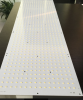
Maybe it is because people are used to Samsung strips, Bridgelux strips, Citizen cobs, Cree cobs, Veros, Luminus cobs etc, all having something in common, they all lack live copper around the mounting holes.
The original point of my post was to let everyone know that these boards require some extra safety attention.
Aka did you spec the aluminum for the board? if not, great its softer than other stuff you have worked with....again what is your point?
I was talking about the silkscreen not the aluminium.
Specifying aluminium grade from a Chinese factory for a small order, good luck with that.
For your form factor board....strip users can use thermal tape :bigjoint:
Well you originally implied that I should have used thermal paste to avoid over tightening but now you are saying it is not necessary for my form factor, I'm confused.
Sure strip users can use thermal tape they can also use thermal paste to avoid over tightening if screws are used right?
same...poor assembly practice...a dot of blue on the threads..no retighten
If you are trying to prevent loosening of screws during vibration or thermal cycling then it is actually better practice to use self-locking fasteners than thread-locking sealants due to the unknown chemical nature of various sealants.

But I was not implying re-tightening for the purpose above but rather because heating/cooling causes the thermal paste to flow, spread, fill the tiny gaps and set. this reduces the tension of boards to heat-sink so it is ''good practice" to tighten them after the first heat cycle.

And overall even if it where poor practice to not use "a dot of blue" it shouldn't be life threatening to re-tighten the board right?
 
Last edited:

conversekidz

Well-Known Member
To my understanding a flat washer and a lock washer are still electrically conductive and not really an "isolation barrier" as conversekidz is recommending. Like a rubber/nylon washer.
assuming you don't engineer....

you are correct that a "metal" flat washer and a "metal" lock washer are electrically conductive, all be there are nylon alternates they are not needed.

so assuming a "metal" flat washer (with rounded edge, nothing to cut surface) and a "metal" lock washer...

The flat washer against the silk screen is the isolation barrier from the screw head, the addition of the lock washer is to 1:ensure the screw stays in place, and 2: to ensure one does not over tighten and damage the silk screen below. If you tighten the screw to the point the lock washer is completely flat and twisting the flat washer below, you good sir have over tightened that screw.

and

nfhiggs example was of poor assembly practices (which was a great example by the way, thanks nfhiggs!), so i'm pretty sure a 2-3 billion a year company knows how to spec something, such a a metal flat washer then a metal lock washer then a nut..the metal washer etc in the example is/was/still is the isolation barrier...
 

nfhiggs

Well-Known Member
To my understanding a flat washer and a lock washer are still electrically conductive and not really an "isolation barrier" as conversekidz is recommending. Like a rubber/nylon washer.
The solder mask is the electrical isolation. You generally want to avoid doing things that will damage that. That's the purpose of the flat washer.

Also that is pretty stupid since one of the main functions of a lock washer is to puncture and grip the surface. Which is why they are also used for earthing.
Depends on the usage - If the screw head is against a chassis or metal frame that's fine, but if the screw is against a circuit board you generally do NOT want the surface of the board damaged, so the flat washer goes under it - that is simply standard usage in the industry. I could show you literally hundreds of tech manuals with exploded diagrams showing Screw>Lock washer>Flat washer for assembly of electronic parts. The lock washer still does its job, which is to reduce the tendency of the screw/nut to back out.
 

DankaDank

Well-Known Member
you are correct that a "metal" flat washer and a "metal" lock washer are electrically conductive, all be there are nylon alternates they are not needed.

so assuming a "metal" flat washer (with rounded edge, nothing to cut surface) and a "metal" lock washer...

The flat washer against the silk screen is the isolation barrier from the screw head, the addition of the lock washer is to 1:ensure the screw stays in place, and 2: to ensure one does not over tighten and damage the silk screen below. If you tighten the screw to the point the lock washer is completely flat and twisting the flat washer below, you good sir have over tightened that screw.
Sure a flat washer would be better than just flat shoulder screw head but by how much i don't know, You would still be applying considerable force of a conductive material against minimal protection to the copper. I have used a bolt->lock washer-> flat washer on aluminium and when dissembled the flat washer has still imprinted itself in the aluminium. I would not recommend using a conductive washer on these boards to anyone.

The solder mask is the electrical isolation. You generally want to avoid doing things that will damage that.
Like placing it along with the copper, around a mounting hole maybe?
Depends on the usage - If the screw head is against a chassis or metal frame that's fine, but if the screw is against a circuit board you generally do NOT want the surface of the board damaged, so the flat washer goes under it - that is simply standard usage in the industry. I could show you literally hundreds of tech manuals with exploded diagrams showing Screw>Lock washer>Flat washer for assembly of electronic parts. The lock washer still does its job, which is to reduce the tendency of the screw/nut to back out.
Yes I know this I don't understand why your are elaborating it, got it the first time. I was saying it is stupid to use a lock washer without a flat washer between it and the PCB or use it on the PCB side instead of against a chassis or metal frame.
 
Last edited:

Ryante55

Well-Known Member
Would anyone be interested in a 6"x16" board with 460 diodes 52-54v 3900ma max? I got some samples was thinking about ordering 100 of them but I don't need that many. Price would probably be around $75
 

vidrose

Active Member
Depends on the designer's objectives.
I just did my first prototype 561c board to see what it would be like to etch from a blank board, Its kind of funny this topic came up as that was one of the FIRST things i looked at and thought to myself, well i f*cked that one up, by not etching any of the copper from the mounting areas. Lmao. I do like chucks board layout, I wonder if theirs a shareware gerber file for it. I have some .062 Fr4 double sided id like to Diy with here soon. I looked into fiber washers too for the screws, I think there made of gold the hardware wanted like .50 cents a piece for them, F that, just build the board right the first time and make room for the screws, a no brainer there.
 
Last edited:

PhenoMenal

Well-Known Member
today i did some tests with power meter + light meter, which was sitting 14" under a 2xQB304, to see the range now that i've added a potentiometer for dimming.
(misc: 240V power. 10k resistor before 100k ohm rotary linear taper potentiometer)

In short, when the dial is on 0 it's drawing 26W and light meter is receiving 7750 lux (i love turning down to this when i need to do any maintenance!)
When the dial is on full (~8.3) it's drawing 253W and light meter is receiving 74600 lux.

LM561C's are 0.3W each ... (2 boards x 304 diodes) x 0.3W = 182.4W total, so I dont understand why it's drawing 253W @ 100%, is that the driver overhead? (253 - 182.4 = 70.6W @ 100%?)

I havent added the potentiometer to my other 2xQB304 yet, but that's drawing 255W so only 2W more than the potted one, though I'm not sure what it was drawing before i added the pot.

Code:
2xQB-304 potentiometer positions, light meter @ 14"...

#   LUX     L%  WATTS  W%  L/W  AMPS
0   7750    10   26    10  298  0.203
1   11730   16   38    15  308  0.238
2   22500   30   70    28  321  0.346
3   32000   43   99    39  323  0.449
4   41200   55   129   50  319  0.566
5   50100   67   161   64  311  0.689
6   60200   80   197   78  305  0.828
7   70700   95   238   94  297  0.997
8   74600  100   253  100  294  1.065
Here's a pretty graph of the Watts vs Lux, each node is a # on the dimmer (0 to 8):


Efficiency graph -- lux per watt ...

So this 2xQB304 at 100% gives 74600 lux @ 14" for 253W. According to the lux per watt data though...
  • 2 x 2xQB304's, both running @ 50% power would output 41200 x 2 = 82400 lux (9.46% more lux for the exact same wattage, and running cooler)
  • 2 x 2xQB304's, both running @ 114W (45%), would output the same 74600 lux for only 114 x 2 = 228W (saving 25W = 9.8% less energy for the exact same lux, and running cooler)
Damn i love dimmability, and damn i love my quantum boards!
 
Last edited:

chuckduck

Well-Known Member
Just realized I never posted pics of my finished build. I'll try to get that posted tonight. In the meantime Jeff got ahold of me again and is trying to sell me these.

Pcb size:900*280mm,40s13p lm561c S6 diode.
20s4p Osram 660nm diodes.this design mixed lm561c diode with Osram LED.
Screen Shot 2018-04-13 at 8.31.43 AM.png


This too.
PCB details:900*280mm,50s16p total 800led,output voltage:135-145v@2400ma,300wattage

Screen Shot 2018-04-13 at 8.35.18 AM.png
 
Top