I solder them. I have been doing low volume. I moved out of a house with a electronics manufacturing line. I left it behind figuring I would never do manufacturing again.
I moved over a year ago. I am renting a house and I may have to move again soon. I need to buy another pick and place robot to put the LEDs on the board. But I need some stability.
For now I use a syringe to put the solder on the pads, drop the LEDs on with a tweezers, and put the boards in my kitchen oven to solder.
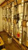
This is my garage March 4, 2016 at about 2:00am. The moving van was packed. This pic was taken minutes before I left my house for the last time. This is what was left behind plus a bedroom that was converted to a workroom has a lot of stuff in it too. Like a manual pick and place machine.
View attachment 3973659