Watercooled Smart IC COB LED Build

ttystikk

Well-Known Member
It's worse than that. It's a $300,000+ house. I had $800,000 in code enforcement fines. I have this issue with authority. I sold it for $15,000 and walked away. And walked away happy. I really did not give a fuck. The fines were from a few minor things, motorcycle trailer, left over roofing tiles stacked next to house, and some over grown trees. Each one of those $150 per day. For years. I owed about $100,000 on the mortgage. My daughter thought I did not leave enough behind. When she moves, she leaves almost everything behind.


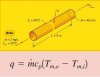
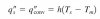
Too thick. Thinner is better. In the thermal flux formula the thickness in this case is the length. The area is the side of the extrusion.

Also if you put some obstructions inside to give the water flow some turbulence, big plus in convective heat transfer.
It had to be that thick for drilling blind holes for mounting chips, lens holders and driver without penetrating the water jacket. Aluminum has good heat conductance properties, thinner would have made for a much more fragile and finicky component.

I deliberately overbuilt the modules to the point where they can be filled with water, capped and run without circulating any water at all. They get plenty warm but not so hot that the electronics are damaged.

Sorry about the loss of your home over something so asinine.
 

ttystikk

Well-Known Member
I like that. I like that a lot. I never thought to do it like that. I always thought there was too much wasted cubic space.

The distance between plants and lights is at a premium. How close can you get the lights to the plants?
Lenses effectively solve the proximity problem.
 

NoFucks2Give

Well-Known Member
I'm thinking along the lines of how an engine uses a thermostat to restrict the water flow so it has more time to absorb heat as it flows through the block
I thought about this for some time. I do not think slowing the flow would help.
The heat transfer is via fluid convection where the water velocity increases the thermal energy exchange.

To verify I got out my textbook Introduction to Thermal Systems Engineering: Thermodynamics, Fluid Mechanics, and Heat Transfer

Most heat transfer systems concentrate on temperature in and out of the tube. You can slow the flow velocity to raise the temperature out but that will also reduce the convective thermal energy flowing from the surface of the tube to the water.

There is no conductive heat exchange. If no water were flowing the heat exchange would be via free convection.


I am only interested in the energy transfer through the copper pipe designated by q in the following diagram.

diagramForcedFluidConvectionTube.jpg

q = thermal energy transfer copper to water
m = flow velocity (mass/s)
c = constant thermal properties of fluid
Tmi = mean temperature in
Tmo = mean temperature out


If temperature in and out remain relatively constant, then
energy transfer q will increase with an increase in flow velocity m.


The velocity of the flow will affect the temperature of the water out of the pipe.
Water temperature will rise if water velocity is reduced.
That will have a negative effect on the transfer of heat from the surface of the tube to the water.
And we do not want the temperature of the water to increase.
As the water temperature increases the convective thermal energy flow rate is reduced by the lower delta between surface and water temperature due to...

Newton's Law of Cooling (aka convection rate equation)

formulaNewtonsLawCooling.jpg

where h = convection coefficient (flow rate, properties of tube material and fluid)

Ts = surface temperature of tube
Tm = mean fluid temperature

Convection energy transfer increases with a greater difference between tube surface and mean fluid temperature.

So a higher fluid velocity
  • increases convection and keeps water and LED cooler
  • cooler water increases delta between water and LED increasing thermal energy flux

to verify the finding in the textbook I made more measurements.


New measurements: two PCBs soldered to same copper water pipe

red 34V @ 700mA = 23.8 W
deep red 36V @ 600mA = 21.6 W

Total Watts = 45.4

setupThermalRed.jpg

Measurements with ice water at the points shown below.
From thermal pad (left most) to copper tube (right most) as indicated by the yellow dots.

Heat from LED mostly flows on top side of PCB but bottom side measurements closely resembles top side temperatures

BOTTOM SIDE OF PCB (deep red - red)
23-21°C Thermal pad
20°C Copper pad
9-13°C Next to screw head
7-10°C Copper bar
6-6°C Solder joint
5-5°C Surface of pipe

TOP SIDE OF Red PCB (ice almost melted)
21°C Copper Pad
12°C Copper Bar
10°C Surface of pipe
5°C Water


measurePoints.jpg


BOTTOM Red PCB WARM WATER (30°C) ambient 27°C
45°C Thermal pad

38°C Copper pad
35°C Next to screw head
31°C Copper bar
30°C Surface of pipe


FULL FLOW RATE vs HALF FLOW RATE

I use two pumps so I disconnected one to see the difference.

With water temp 17°C
Thermal Pad @ full flow rate, = 27°C
Thermal Pad @ half flow rate = 32°C


Godfather420

Well-Known Member
Also if you put some obstructions inside to give the water flow some turbulence, big plus in convective heat transfer.
I'm Planning to twist aluminum tape the length of my lights. Straight shot water blocks offer TERRIBLE thermal transfer. And custom made turbulaters are unrealistically expensive.
 
Last edited:

ttystikk

Well-Known Member
Also if you put some obstructions inside to give the water flow some turbulence, big plus in convective heat transfer.
I'm Planning to twist aluminum tape the length of my lights. Straight shot water blocks offer TERRIBLE thermal transfer. And custom made turbulaters are unrealistically expensive.[/QUOTE]
Try one with and one without. I doubt it will make much difference.
 

mahiluana

Well-Known Member
I am only interested in the energy transfer through the copper pipe designated by q in the following diagram.


q = thermal energy transfer copper to water
m = flow velocity (mass/s)
c = constant thermal properties of fluid
Tmi = mean temperature in
Tmo = mean temperature out
*************************************************
:peace::fire: Is it not easier just to use an amount of water (eg. 10kg) in a closed circuit -
and then measure time and rising temperature of water ?

or simply use a heat meter (flow-heat-module)

http://www.ebay.de/itm/Waermemengenzaehler-Hydrometer-Sharky-775-Ultraschall-Qn-1-5-2-5-Waermezaehler/192178665186?rt=nc

With led-light you will always transform 75-80% into heat and 20-25% into light.
You can seperate 3 main areas where this heat will dissipate:

upper side of led chip ---> to air
led platine to metall tube ---> to air
led platine to metall tube ---> to water

Heat resistance is an important factor in heat management.
If we use thermal grease or glue to mount the chip on the tube -
we can do it well - or not. ---> Tj. of your chip will be low - or not.

So I think that it is not easy - or possible - or usefull to calculate the heat transfer
from copper to water by diameter and lenght of your tube, because too many other parameters
have influence to your result. --- just measure it ^.

My suggestion to blow away any problems with heat resistance is still -
to drill an adequate hole into the tube and seal it well with the chip platine.

https://www.rollitup.org/attachments/s6001989-jpg.3950444/


This will give you a max. of heat exchange into the water and a max. of low chip temp.
And maximum means: worldrecord in energy efficiency "and" worldrecord in light-effiency
by lowest chip temps.

- and again -- and again -- there is no worldrecord in energy efficiency
if you don`t use the hot water.

So I suggest to use this hot water in combination with a heat exchanger to receive free hot water for heating, shower, kitchen, swimming pool, fishtank and/or others..............:fire::peace::bigjoint:
 

caracara

Member
I'm Planning to twist aluminum tape the length of my lights. Straight shot water blocks offer TERRIBLE thermal transfer. And custom made turbulaters are unrealistically expensive.
Try one with and one without. I doubt it will make much difference.[/QUOTE]

Sweet setup you have there ttystikk! I especially like the overbuilding with passive convection as a failsafe. That much wattage would make me paranoid without a lot of margin for error.
What water flow rate (gallons per hour) are you using through the 2"x4" bar? I'm thinking of doing something similar, but am not sure what size water pump to use with that kind of tube cross-section. Have you experimented with different flow rates?
 

ttystikk

Well-Known Member
Sweet setup you have there ttystikk! I especially like the overbuilding with passive convection as a failsafe. That much wattage would make me paranoid without a lot of margin for error.
What water flow rate (gallons per hour) are you using through the 2"x4" bar? I'm thinking of doing something similar, but am not sure what size water pump to use with that kind of tube cross-section. Have you experimented with different flow rates?
My design requirement was just to get enough flow to carry the heat away. I don't have any flow rate numbers for you. Water is so thermally dense that low flow rates work fine.
 

ttystikk

Well-Known Member
*************************************************
:peace::fire: Is it not easier just to use an amount of water (eg. 10kg) in a closed circuit -
and then measure time and rising temperature of water ?

or simply use a heat meter (flow-heat-module)

http://www.ebay.de/itm/Waermemengenzaehler-Hydrometer-Sharky-775-Ultraschall-Qn-1-5-2-5-Waermezaehler/192178665186?rt=nc

With led-light you will always transform 75-80% into heat and 20-25% into light.
You can seperate 3 main areas where this heat will dissipate:

upper side of led chip ---> to air
led platine to metall tube ---> to air
led platine to metall tube ---> to water

Heat resistance is an important factor in heat management.
If we use thermal grease or glue to mount the chip on the tube -
we can do it well - or not. ---> Tj. of your chip will be low - or not.

So I think that it is not easy - or possible - or usefull to calculate the heat transfer
from copper to water by diameter and lenght of your tube, because too many other parameters
have influence to your result. --- just measure it ^.

My suggestion to blow away any problems with heat resistance is still -
to drill an adequate hole into the tube and seal it well with the chip platine.

https://www.rollitup.org/attachments/s6001989-jpg.3950444/


This will give you a max. of heat exchange into the water and a max. of low chip temp.
And maximum means: worldrecord in energy efficiency "and" worldrecord in light-effiency
by lowest chip temps.

- and again -- and again -- there is no worldrecord in energy efficiency
if you don`t use the hot water.

So I suggest to use this hot water in combination with a heat exchanger to receive free hot water for heating, shower, kitchen, swimming pool, fishtank and/or others..............:fire::peace::bigjoint:
It all depends on how hot your hot water is.

Cool temps for best chip efficiency is not suitable for doing dishes.

Frankly, cool temps for max chip efficiency isn't great for growing temperatures, either.
 

mahiluana

Well-Known Member
how hot your hot water
:peace: - My water temps. are 16°C - 37°C.
My chip platines (Tj) i guess ~ 5°C higher.
If you run your grow room at ~26-28°C - there are no problems with condensation
or too much heat - I need very low quantities of fresh (cold) air and water.
:bigjoint:
 

mahiluana

Well-Known Member
That just means
:peace: ...that you should read before and after....


Thermal Management of Cree XLamp® LEDs
Heat generation
LEDs generate visible light when current passes across the junction of the semiconductor chip. However, LEDs are not 100% efficient;
much of the power running through an LED is output as heat, which thus needs to be dissipated. Cree royal blue XLamp LEDs are over 50%
efficient and white XLamp LEDs are over 40% efficient. That is, under normal operating conditions, approximately 50% to 60% of the input
power is output as heat, while the rest of the input power is converted to light. To be conservative, assume LEDs convert 25% of the input
power to light and output 75% of the input power as heat. This estimate varies depending on current density, brightness and component,
but is a good estimate for thermal design. Equation 1 below shows how to calculate the thermal power.
Pt = 0.75 Vf If
Equation 1: Thermal power calculation
where:
Pt is the thermal power (W)
Vf is the forward voltage of the LED (V)
If is the source current to the LED (A)
The Vf and If can be measured directly or calculated from the PCT, so the thermal power can easily be calculated. This is the amount of
power the system/heat sink must dissipate.

*****************************
If you don`t believe in CREE
have a look here:
https://www.rollitup.org/t/heat-from-1200w-of-1212s-vero-29s-cxm-22-cxb3590-compared-to-2x-600w.936071/page-2


You can measure "your" most efficient led chip in a quick, low cost experiement and
tell us your result(s).


Attachments

wietefras

Well-Known Member
Oh holy noodliness no. Not another noob with wild claims that are just pure nonsense. Will it never end?

Just read a few posts lower for an explanation of the difference between dissipated heat by the COB (which actually needs to be cooled by the heat sink) and the Laws of thermal dynamics.
 

ttystikk

Well-Known Member
:peace: ...that you should read before and after....


Thermal Management of Cree XLamp® LEDs
Heat generation
LEDs generate visible light when current passes across the junction of the semiconductor chip. However, LEDs are not 100% efficient;
much of the power running through an LED is output as heat, which thus needs to be dissipated. Cree royal blue XLamp LEDs are over 50%
efficient and white XLamp LEDs are over 40% efficient. That is, under normal operating conditions, approximately 50% to 60% of the input
power is output as heat, while the rest of the input power is converted to light. To be conservative, assume LEDs convert 25% of the input
power to light and output 75% of the input power as heat. This estimate varies depending on current density, brightness and component,
but is a good estimate for thermal design. Equation 1 below shows how to calculate the thermal power.
Pt = 0.75 Vf If
Equation 1: Thermal power calculation
where:
Pt is the thermal power (W)
Vf is the forward voltage of the LED (V)
If is the source current to the LED (A)
The Vf and If can be measured directly or calculated from the PCT, so the thermal power can easily be calculated. This is the amount of
power the system/heat sink must dissipate.

*****************************
If you don`t believe in CREE
have a look here:
https://www.rollitup.org/t/heat-from-1200w-of-1212s-vero-29s-cxm-22-cxb3590-compared-to-2x-600w.936071/page-2


You can measure "your" most efficient led chip in a quick, low cost experiement and
tell us your result(s).

The confusion comes from the fact that the light turns into heat as well, when it hits something.

This means that every watt consumed must be accounted for, not just a percentage.
 

mahiluana

Well-Known Member
This means that every watt consumed must be accounted for, not just a percentage.
:peace: hi mr. ttystikk - sorry to mention, that all the sticky flowers we are talking about
here in rollitup - are a result of light-input, so light is not always transformed to heat.
In our case - THC & Co. is chemicaly stored light energy.
With PV panels you can charge your electric car and transform light into movement.

But you are right - heat is a very dominant form of energy, as we can see by the rising global temperature. But I guess you also still doubt, that even the most efficient CREE chip(or whatever)
produce > 70% of heat ? :eyesmoke::?:
 

mahiluana

Well-Known Member
another noob with wild claims
@wietefras ?? Are you dyslexic ??

The dissapointment is on my side.

- you never did a watercooled build ! I did many times
- you never measured the heat of a led chip ! I did many times
- you never read this link - as I told you 5 times 5 month ago ! I did many times

http://www.cree.com/led-components/media/documents/XLampThermalManagement.pdf

Thermal Management of Cree XLamp® LEDs
Heat generation
LEDs generate visible light when current passes across the junction of the semiconductor chip. However, LEDs are not 100% efficient;
much of the power running through an LED is output as heat, which thus needs to be dissipated. Cree royal blue XLamp LEDs are over 50%
efficient and white XLamp LEDs are over 40% efficient. That is, under normal operating conditions, approximately 50% to 60% of the input
power is output as heat, while the rest of the input power is converted to light. To be conservative, assume LEDs convert 25% of the input
power to light and output 75% of the input power as heat. This estimate varies depending on current density, brightness and component,
but is a good estimate for thermal design. Equation 1 below shows how to calculate the thermal power.

Pt = 0.75 Vf If !!!!!!!!!!!!

Equation 1: Thermal power calculation
where:
Pt is the thermal power (W)
Vf is the forward voltage of the LED (V)
If is the source current to the LED (A)
The Vf and If can be measured directly or calculated from the PCT, so the thermal power can easily be calculated. This is the amount of
power the system/heat sink must dissipate.
 
Top