I want to built an LED grow light from scratch but I'm not sure what to look for when wiring in series and parallel on the same board.
I want it to have different types of LEDs with different wavelength, like the Spider Farmer SF4000 or the SSK-272-RR-V2 for example, so I have to deal with different voltages and currents needed.
What do I have to look for when wiring series (of LEDs) in parallel when it comes to the forward voltage U_f (V) and forward current I_f (A) of the loads?
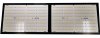
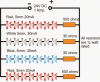
I tryed to find a schematic but didn't so I tryed to look for the paths in the LED light PCB. From the SSK-272-RR-V2 I could see a lot of them in the pictures found online and so I made a scetch. Here the simplistic
Installed are:
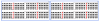
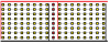
256 Nichia 757, NFSW757H-V1 [U_f: 2.84 V, I_f: 65 mA, I_max: 180 mA] warm whites (black squares) and
16 Cree XP-G3, XPGDPR-L1-0000-00F01 [U_f: 1.99 V, I_f: 350 mA, I_max: 1.5 A] 660 nm "photo reds" (red squares)
Then I tryed to calculate and see how they did it.
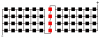
The whites are wired in series of four, the reds parallel in four.
When I look at one quart of the board and would try to drive it, my thoughts are:
- in parallel wiring, every row sees the same voltage U, so to run them, I have to put at least 11.36 V on the circuit because of the series of whites adding up (4x 2.84 V = 11.36 V to deliver U_f)
- that means that the reds will get 11.36 V in parallel too, the U_f of this part is just 1.99 V as of parallel wiring but the I_f is 1.4 A (4x 350 mA)
My question now is (if I am right so far is another one): where does more energy travel? The way of lower current needed, or the way of lower voltage needed?
I tryed to find the way of least resistance (literally) and calculated R=U/I:
series of 4 whites: 11.36 V, 65 mA -> R=174.77 Ohm
parallel of 4 reds: 1.99 V, 1.4 A -> R=1.42 Ohm
so in my mind there would be much more current flow through the red LEDs in parallel, maybe with a CC driver set to 1.5 A on a safe level (because it could take 4x I_max: 1.5 A=6 A), but the white LEDs would run way under there capacity.
What do I have to take in account when planning such a circuit regarding different V_f and I_f values?
Where am I wrong? I think have miscalculated the resistances (1/R=1/R_1+1/R_2+1/R_n)
I want it to have different types of LEDs with different wavelength, like the Spider Farmer SF4000 or the SSK-272-RR-V2 for example, so I have to deal with different voltages and currents needed.
What do I have to look for when wiring series (of LEDs) in parallel when it comes to the forward voltage U_f (V) and forward current I_f (A) of the loads?
I tryed to find a schematic but didn't so I tryed to look for the paths in the LED light PCB. From the SSK-272-RR-V2 I could see a lot of them in the pictures found online and so I made a scetch. Here the simplistic
as I guessed it.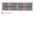
(didn't know how to cut with linux draw, will pretty it up in the future)
(didn't know how to cut with linux draw, will pretty it up in the future)
256 Nichia 757, NFSW757H-V1 [U_f: 2.84 V, I_f: 65 mA, I_max: 180 mA] warm whites (black squares) and
16 Cree XP-G3, XPGDPR-L1-0000-00F01 [U_f: 1.99 V, I_f: 350 mA, I_max: 1.5 A] 660 nm "photo reds" (red squares)
Then I tryed to calculate and see how they did it.
The whites are wired in series of four, the reds parallel in four.
When I look at one quart of the board and would try to drive it, my thoughts are:
- in parallel wiring, every row sees the same voltage U, so to run them, I have to put at least 11.36 V on the circuit because of the series of whites adding up (4x 2.84 V = 11.36 V to deliver U_f)
- that means that the reds will get 11.36 V in parallel too, the U_f of this part is just 1.99 V as of parallel wiring but the I_f is 1.4 A (4x 350 mA)
My question now is (if I am right so far is another one): where does more energy travel? The way of lower current needed, or the way of lower voltage needed?
I tryed to find the way of least resistance (literally) and calculated R=U/I:
series of 4 whites: 11.36 V, 65 mA -> R=174.77 Ohm
parallel of 4 reds: 1.99 V, 1.4 A -> R=1.42 Ohm
so in my mind there would be much more current flow through the red LEDs in parallel, maybe with a CC driver set to 1.5 A on a safe level (because it could take 4x I_max: 1.5 A=6 A), but the white LEDs would run way under there capacity.
What do I have to take in account when planning such a circuit regarding different V_f and I_f values?
Where am I wrong? I think have miscalculated the resistances (1/R=1/R_1+1/R_2+1/R_n)