Any one using ERP led drivers

GrowLightResearch

Well-Known Member
Untitled3.jpg

Do you seriously not understand the difference between this (which is where those charts are from)
Difficult to take you seriously because you do not get it.

Does the Mean Well driver not have a Buck controller chip?


The green waveform is labeled ILED

Because This


Untitled2.jpg


Came from this:

Where what is being measured is highlighted in yellow. The current through the inductor and LEDs.
All Buck step down regulators operate pretty much the same.
The Mean Well is a Buck step down regulator.


Untitled.jpg
 

GrowLightResearch

Well-Known Member
Meanwell 3 in 1 dimming is via Constant Current Regulation which reduces the amplitude of the current.
Constant Current Regulation in a switching driver (Mean Well is a switcher) the current is regulated by changing the duty cycle of the output. The amplitude remains the same and the current is averaged. Only an inefficient linear driver adjusts the amplitude.

Follow the highlighted arrows from the 3 in 1 dimmer wires to the PWM circuit. Mean Well uses PWM for their 3 in 1 dimming.


PurpleBuz

Well-Known Member
Constant Current Regulation in a switching driver (Mean Well is a switcher) the current is regulated by changing the duty cycle of the output.
Nonsense

https://www.power-supplies-australia.com.au/blog/common-problems-dimming-mean-well-led-drivers

https://www.adminstrumentengineering.com.au/instrument-engineering-news/dimming-with-the-mean-well-hlg-and-lpf-d-led-drivers

and finally from Meanwell themselves ... http://www.meanwell.eu/ExclusivePDF/DRIVER_DIM_STRIP.pdf

Figure 1. Mean Well amplitude current adjusting LED driver HLG-100 connected to LED strip at different load (length) conditions: (a) full load(length) resulting in the best dimming performance; (b) 70% load(length) implying non-perfect dimming experience due to small dead travel; (c) 30% load(length) implying worst dimming result due to huge dead travel.
 
Last edited:

sethimus

Well-Known Member
those stupid people at meanwell dont know how their drivers work, only the mighty cuntlightresearch knows EVERYTHING!
 

wietefras

Well-Known Member
Difficult to take you seriously because you do not get it.
Yeah right. You have been wrong about everything you said since you came here, but I'm the one who doesn't get it.

Does the Mean Well driver not have a Buck controller chip?
What's behind the "buck driver" in that Mean Well schematic? It's in the damn schematic you posted and I explicitly explained that bit of the schematic to you.

It's just frightening how consistently blind for the truth you are.

You clearly know nothing about light, reflection or leds, but the only thing about you that I slightly believed was that you might have done something in electronics. I guess not even that. First of all that discussion with nfhiggs where you were completely and utterly wrong and now this nonsense about a buck driver chip compared to a full driver. Anyone who had worked even for 5 minutes in electronics would know how easy it is to turn a PWM signal into a steady voltage. Of course a premium driver like these would omit such a reasonably simple fix. Even though it's depicted in the schematic! /s

So it's getting more and more clear that the only thing you really are is a pathological liar. You have no experience and no skills whatsoever. Unless annoying a whole forum with a relentless stream of bullshit could be considered a skill.
 
Last edited:

Greengenes707

Well-Known Member
The output current is indeed actually reduced, not PWM. This is shown in the real world by the efficacy gains in systems when dimming. PWM output will not improve efficacy because the chips are still driven at the same current full power or dimmed, just duty cycle adjustments.
 

GrowLightResearch

Well-Known Member
What's behind the "buck driver" in that Mean Well schematic?
It's not what's behind the buck circuit in the Mean Well, it's what's in front of it. The buck driver is the last stage, the output.
I explicitly explained that bit of the schematic to you.
You did not explain jack shit.

Anyone who had worked even for 5 minutes in electronics would know how easy it is to turn a PWM signal into a steady voltage
I'm an electrical engineer, you are not, and you think you can explain how a buck driver works? You are delusional.
You must have delusions of adequacy.
Steady voltage? I guess you do not understand the difference between a DC-DC converter and a constant current source.

Your ignorance is monumental.
 

nfhiggs

Well-Known Member
Without PWM how is the current reduced? Current is regulated 100% by PWM whether or not the driver has a dimmer.
I think what he was saying is that the actual output current (in the load) does not consist of pulses that are reduced in width to dim - the output is filtered and smoothed out by that point.
 

PurpleBuz

Well-Known Member
So why were the arrows from the dim wires going to the PWM circuit?
Why is there a PWM circuit?
WTF do the links you posted have to do with the topic? Are you changing the topic?
the links prove you have misstated facts. meanwell 3 in 1 dimming functions by changing the amplitude of the current. NOT by changing the duty cycle.

Apparently you do not know how to read or you choose NOT to read when you are wrong.
 

GrowLightResearch

Well-Known Member
amplitude of the current. NOT by changing the duty cycle.
Like in AC voltage there is a peak to peak and an RMS value.
In a driver the peak amplitude remains the same and the average or effective current changes based on the width of the current pluses. In an HLG the pulses come at at rate of 100 KHz. The width of the pulse has a duty cycle of 0-100%. Or nearly. some drivers need at least a negative spike (100%) and or positive spike (0%).

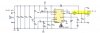
All switching power supplies, voltage or current, use PWM to regulate the voltage or current. The switching signal's duty cycle is varied for regulation. The PWM switching signal is typically generated by an oscillator circuit with in the regulator chip. Most drivers fix the PWM switching frequency to a value that is compatible with the output inductor for maximum efficiency. Some will dynamically vary the frequency based on the load. Efficiency is a function of the switching frequency, the on resistance of the output FET, inductance of output inductor, and series resistance of the inductor. To maintain efficiency the switching frequency is fixed to balance with the inductance. The only means left is to modulate the pulse width for regulation.

Mean Well's 3 in 1 dimming is really only one circuit that uses a voltage reference to set the PWM duty cycle.
When the reference voltage is at 10v the duty cycle is 100%.
When the reference voltage is at 0v the duty cycle is (or near) 0%.

There is a weak pull-up resistor connected to an internal 10v source.
When a resistor is connected the resistor creates a voltage divider with the pull-up resistor.
When left open the reference voltage is pulled up to 10v by the pull-up resistor.
When a voltage source between 0 and 10v is applied, it over-rides the pull-up resistor's 10v.
When the applied voltage is alternated between 0 and 10v the duty is also alternated between 0 and 100%.

Their 3 in 1 dimming is patented but a quick patent search I conducted did not find it.
If someone can find it, I am sure it works as I described.
There is very little difference between one switching LED driver design and another. They all use PWM to regulate the current. A CC driver cannot regulate voltage as the voltage is determined by the forward voltage of the LED string. The current is typically sensed by a shunt resistor.

I think what he was saying is that the actual output current (in the load) does not consist of pulses that are reduced in width to dim - the output is filtered and smoothed out by that point.
Typically an LED driver's output has the pulses. How much they are "smoothed" is indicated by the ripple current spec in the datasheet. Mean Well does not spec current ripple but rather peak to peak voltage ripple which is a spec for a DC voltage supply.

Additionally there is conduction mode. A driver in continuous conduction mode will look like the ripple is elevated to the middle of the signal as shown in the green waveform previously posted. When in discontinuous conduction mode the output reaches ground. Do a Google image search for discontinuous conduction mode.
 
Last edited:

GrowLightResearch

Well-Known Member
the links prove you have misstated facts. meanwell 3 in 1 dimming functions by changing the amplitude of the current. NOT by changing the duty cycle.
No matter how many times you say it does not make it true. The output current is ONLY changed by the duty cycle of the switching signal. The duty cycle can be alternated between 0% and 100%, but it's still the duty of the switching FET that changes.
 

diyled

Well-Known Member
I think he has some issues....

Anyway....Does anybody have any info for this ERP Driver VLB260W-48

Ive emailed them but no response yet and i just cant find any data anywhere.
 

wietefras

Well-Known Member
It's not what's behind the buck circuit in the Mean Well, it's what's in front of it. The buck driver is the last stage, the output.
It's clearly not.

You posted the schematics and complained that the power switching controlled by the PWM circuit might output a PWM signal. After the power switching, which component do you still see?


Or are you that dumb that you think the OLP detector is somehow driving the output?

Your ignorance is monumental.
The irony.
 

PurpleBuz

Well-Known Member
No matter how many times you say it does not make it true. The output current is ONLY changed by the duty cycle of the switching signal. The duty cycle can be alternated between 0% and 100%, but it's still the duty of the switching FET that changes.
stop blathering irrelevant nonsense.

If you are so convinced that the Meanwell 3 in 1 dimming as deployed in the HLG drivers is PWM output dimming then put a multimeter on the current output and measure the duty cycle when its dimmed and when its not dimmed. Meanwell itself has stated that the output current is dimmed by lowering the amplitude of the current.

Nobody cares what is happening inside the meanwell black box labeled as PWM control. What we care about is
- does the driver dim
- how to control the drivers dimming
- is it PWM out, is it controlling the "amplitude of the output current" to dim the output or something else.

For my purposes I do not want a PWM output. because I want the current through the led to be lower rather than to be strobed at the max current since leds are more efficient at lower currents. The color shift associated with lower currents is insignificant for plants.
 
Last edited:

ANC

Well-Known Member
I have nothing but good things to say about the Delta range of drivers from Digikey.
They are even a bit cheaper than the HLG series and the adjustment screws are positioned so you can access them from the side, so you don't have to fight with trimpots above your head..

Having actually designed and build LED drivers from LED driver chips, there is quite a lot that goes into the WPM, even the frequency is important if you don't want streaky photos. If I remember correctly you had to stay above 42kH to prevent it.
 

GrowLightResearch

Well-Known Member
meanwell 3 in 1 dimming functions by changing the amplitude of the current. NOT by changing the duty cycle.
output current is dimmed by lowering the amplitude of the current.
Do you know what current amplitude means? I think not.

Google "calculate current amplitude"

Current amplitude can be changed by changing the duty cycle. While peak amplitude remains the same.
 
Last edited:
Top