Arduino Controlled Grow and PC Program - Work In Progress

AdvancedNewbie

Well-Known Member
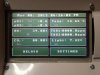
I actually don't use the touch screen any more - just the web interface. But if you're interested in the touch screen, the old 'envirocontrol' version of this project uses the touch screen but is no where near as complete as the newest version. But atleast you can reference from that. The pin connections, the library and other information are available here: http://www.henningkarlsen.com/electronics/library.php?id=51 As for the second timer, I was thinking of making every relay capable of being controlled by timer; on/off/enabled. But everybody's setup's can be quite different from one another, and some modification to the code to make it suit your purpose might be needed.

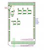
As for the schematics, they are being finalized right now - once everything's verified, we should be able to make our own boards with all the components already connected to one another, or just view the schematic and use the parts you already have. But I will release this when it's done.
 

omnidrive

Member
I understand that you no longer use the touch screen but I do not have the internet endroi of my culture and I want to keep the screen. about actually I noticed that the switch was reversed on the sreen , the top is down and the bottom up, the middle stays in the middle, do you have any idea or it just come ???
I check the connection everything is ok
I use a itdb02 4.3 + arduino mega +itdb02 mega shield, I do not colmprend !
forum if somebody can help me it will be nice Thanks !!!
 

AdvancedNewbie

Well-Known Member
I understand that you no longer use the touch screen but I do not have the internet endroi of my culture and I want to keep the screen. about actually I noticed that the switch was reversed on the sreen , the top is down and the bottom up, the middle stays in the middle, do you have any idea or it just come ???
I check the connection everything is ok
I use a itdb02 4.3 + arduino mega +itdb02 mega shield, I do not colmprend !
forum if somebody can help me it will be nice Thanks !!!
I think I recall adding in a negative sign to make it opposite (the correct way) for my screen. If you fish around the envirocontrol code you'll find there's a function that gets the x/y coordinates of the touch and runs the raw values through a formula to convert to pixels. I may add a screen in the future, but it was hindering the progress of this project and I just wanted to get the functions written and done and the web interface allows for a quicker development time, in my opinion... But, I will probably bring it back later.
 

omnidrive

Member
Here is your beautiful work that I allowed myself to use in for my installation! What do you think? Thanks for the directions for the touch screen, can - you tell me the number of the relevant code line and what is the formula that you use exactly, I'm really newbie and screens I have still problem. Thank you very much.
 

AdvancedNewbie

Well-Known Member
Wow, I wasn't expecting this. Congrats on getting the code up and running, that looks pretty professional.


This is the touchscreen function to get x and y values:
void getXY() {
if (readxy == true) {
x = 999;
y = 999;
readxy = false;
}

if (myTouch.dataAvailable()) {
int sumx = 0;
int sumy = 0;
int i = 0;


for(i = 0; i < 5; i++){
myTouch.read();
sumx = sumx + myTouch.getX();
sumy = sumy + myTouch.getY();
}
x = ((sumx/i) - 50) * 2.5; //Set X Scale here
y = ((sumy/i) - 170) * 1.7; //Set Y Scale here
readxy = true;
}

}

and under void setup() there's this:


//LCD Initial setup
myGLCD.InitLCD(LANDSCAPE);
myGLCD.clrScr();


myTouch.InitTouch(PORTRAIT);
myTouch.setPrecision(PREC_HI);

^^^ See how I had to change myTouch.InitTouch to PORTRAIT instead of LANDSCAPE --> for some reason this corrected the x y values for me (they were inverted) This should get you up and running.
 

Voidling

Well-Known Member
What is a quick cost estimate of getting one of these up and running?

I'll have to go back and look at the capabilities. It's love to be able to set the Times by a pc rather than mechanical timers
 

Voidling

Well-Known Member
Sorry I somehow started in the middle of the thread. I guess just take out the cost of the touchscreen and everything else ids the same
 
AN you never cease to amaze me! I've been busy building my room, working on wiring, plumbing, insulation, etc. while you've been busy writing quite possibly the best grow control program in existence. I haven't had much time to work on my controller project, but I've been slowly gathering the hardware as funds allow. Seeing that you've switched to a Raspberry Pi based setup was very exciting, once I figured out what a Raspi was! Anyhow I went ahead and picked up a Raspi and after getting it booted up on Raspian, found that you've recently made yet another HUGE update. Needless to say I'm quite excited now to get all my pieces put together and working.

I can't begin to thank you enough for all the time and effort that you've put into this project. The new website is great, thanks for putting the image up there, that will make installation/setup a breeze. Once you get a wiring diagram up, it should be easy for anyone with some basic skills to be able to re-create this awesome system you've built.

When using those cheap 120v 10a relay boards from china it might be a good idea to use some fuses to keep everything safe and sound, in case a device attached to them shorts out or something causes the relays to be overloaded beyond their 10a rating. So I bought some used DIN rail mount fuse holders and distribution blocks, the type they use in professional PLC systems, specifically I bought the Allen-Bradley 1492-FB1C30 fuse holders and 1492-W10 distribution blocks. My plan is to use one 20amp circuit to power 10 relays, so there will be 20 distribution blocks divided equally across two DIN rails, one for power and one for neutral. Each rail will have the distro blocks bridged using 10-Position jumpers (Allen-Bradley 1492-CJ8-10). I figure that at the least it will be much cleaner and simpler to hook everything up using the distribution blocks for power and neutral, then a ground bus bar from an old circuit breaker panel to connect all the grounds. Various fuse sizes will be used depending on the amperage draw of the equipment being powered and the power rating of the relay. I'm thinking that without having fuses before the relays, there is a good chance that the devices hooked to them could overload the 10A relay to the 20a max of the circuit breaker, causing damage to the relays or in a worst case scenario fire.
 
@Omnidrive - Where can I get one of those cases? What is the name of the case or what is it supposed to be used for? I've been searching for a metal box for my controller, but that plastic one looks like it might work nicely.
 

omnidrive

Member
If people want to associate with me to develop the touch interface it would be very useful to me. for those who do not have internet on site.
I think that must be continued to develop this part of the project.
What do you think Advancednewbie ???
Is that you can allow the development project touch ? Course in close collaboration with you to this model. I do not allow myself to do it if you do not allow as much I respect your work as you know.
Thank you for everything ;)
 

AdvancedNewbie

Well-Known Member
Hey everybody, thanks for the support. Omni, your setup looks quite professional and well organized, I actually plan on bring back the touchscreen interface soon now that the web interface is coming along quite nicely. I've made a few changes on the Raspberry Pi to keep the wireless connection up at all times and to restart the yieldbuddy program if anything goes wrong - seems very failsafe now. Thanks for the kind words ElginAgain - the fuses are definitely a good idea. There are push-button fuses that you can reset and I'm looking into incorporating those. I've split up the Arduino code to make it much more organized and readable. I've added a CheckSetpoints() function where you can easily write conditions for any custom rules you may want to incorporate, after all - everybody's setup is different... I'm getting excited to bring back the touchscreen - it will mean this project will once again become a fully independent system and will only require the Raspberry Pi for the web interface. Now that the code is all split into separate files it should be eas(y/ier) to add the touchscreen code back into the project.

I've been pretty busy with life, but should find time mid next week to put some serious work into the code once again and progress this project even further. Omni, I plan on re-using the previous 'envirocontrol' touchscreen code and upgrading it a bit - if there's anything you want added or anything you have done yourself which warrants a look at, send me a PM and I'll be happy to collaborate ideas/code. I wish I got the ITDB02; it seems like 'the standard' touchscreen to use in Arduino projects and has the libraries built up already; I am able to use those libraries, but I have to modify the code a bit to get it working properly with my screen. So hopefully it shouldn't be an that big of an issue with your screen - If I recall correctly, the only differences were with the X/Y coordinates from the touch interface, so it should just be a matter of calibrating those formulas to obtain the correct X/Y values for the ITDB02 (as mentioned in a previous post).

If there's anything you guys want implemented just let me know! And thanks again for all the support :)
 

omnidrive

Member
Hello advancednewbie, Here is the diagram of PIN for ITDB02 - 4.3 Itead studio as well as the megashield ITDB02 V2.1: ITDB02_4.3  mega pin definition.jpgITDB02_MEGA_Shield_ V1.2.jpg

Pin d'Arduino
Avec ITDB02
3V3
LED_A
RD
5V
VCC

GND
GND
D22 (PA0)
DB8
-
D23 (PA1)
DB9
-
D24 (PA2)
DB10
-
D25 (PA3)
DB11
-
D26 (PA4)
DB12
-
D27 (AP5)
DB13
-
D28 (PA6)
DB14
-
D29 (AP7)
DB15
-
D37 (PC0)
DB0
-
D36 (PC1)
DB1
-
D35 (PC2)
DB2
-
D34 (PC3)
DB3
-
D33 (PC4)
DB4
-
D32 (PC5)
DB5
-
D31 (PC6)
DB6
-
D30 (PC7)
DB7
-
D41 (PG0)
RAZ
-
D40 (PG1)
CS
-
D39 (PG2)
WR
-
D38 (PD7)
RS
-
D50 (PB3)
SD_OUT
-
D51 (PB2)
SD_IN
-
D52 (PB1)
SD_CLK
-
D53 (PB0)
SD_CS
-
D6
D_CLK
-
D5
D_CS
-
D4
D_IN
-
D3
D_OUT
-
D2
D_IRQ


omnidrive

Member
my sides I'm still stuck with the touchpad, no coordination toujour X / Y for the moment (I have a headache so I'm looking for: (Just a suggestion, I think that several factors should be able to use the timer to be activated and also I want to make a code change to adjust the Real time clock for the irrigation in second , as you know irrigation aeroponics high pressure is in seconds : 20 sec ON/5 Mins OFF is ideal. i'm looking currently have a code for irrigation more spaced to night 20sec On/ 20 mins OFF.
this is the contoleur for irrigation night and day: 7 GSE water timer
http://www.indoorgardens.fr/catalog/fr/programmateurs-timers-145/gse-water-timer-gse-7-1977.html

two irrigation regimes for one day and one night. The timer makes a difference just with a sensitive photocell integrated in the housing. The sensitivity of this cell is adjustable and adapts to disruptions light cycles (5 min " Changeover Time")
watertimerschema.jpg Impulse phase
Off, 1s, 2s, 3s, 4s, 5s, 6s, 7s, 8s, 9s, 10s, 15s, 20s, 25s, 30s, 35s, 40s, 45s, 50s, 55s, 1min., 1.25min.,
1.5min., 1.75min., 2min., 2.25min., 2.5min., 2.75min., 3min., 3.25min., 3.5min., 3.75min., 4min., 4.25min.,
4.5min., 4.75min., 5min., 5.5min., 6min., 6.5min., 7min., 7.5min., 8min., 8.5min., 9min., 9.5min., 10min.,
11min., min., 12min., 13min., 14min., 15min., 16min., 17min., 18min., 19min., 20min.

switch intervalles
1s, 2s, 3s, 4s, 5s, 6s, 7s, 8s, 9s, 10s, 15s, 20s, 25s, 30s, 40s, 50s, 1min. 1.5min., 2min., 2.5min., 3min.,
3.5min., 4min., 4.5min., 5min., 6min., 7min., 8min. ,9min. ,10min., 15min., 20min., 25min., 30min., 35min.,
40min., 45min., 50min., 55min, 1h, 1.5h, 2h, 2.5h, 3h, 3.5h, 4h, 4.5h, 5h, 5.5h, 6h, 6.5h, 7h, 7.5h, 8h, 8.5h,
9h, 9.5h, 10h, 11h, 12h, 13h, 14h, 15h, 16h


Dimensions : 34x58x86mm
Poids : 86g
Volt: 230V / 50Hz
I max. = 2A
Protection class: IP20
 
Top