DIY Lighting, combo CFL/HPS built on the cheap

AlteredEgo

Active Member
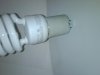
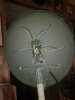
Hello Ya'll! I am in the southwest, and we have loads of sun, so I have been doing a grow this year using the sun through a textured window, and I noted the days shorter than 12 hrs, and lots of cloudy days this year. I needed some supplementary lighting. Being a fabricator at heart, and on a budget of disability income, I started thinking and studying lighting, wavelengths of light, and plant needs etc. I decided since I am flowering now, but might want to mix or change tight types, I decided on CFL's. I thought I'd need a great reflector to direct this light, and enhance the ability of CFL's to project light a little ways from the bulbs, so it can reach a ways.

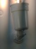
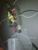
Then, I decided to put a little bit of HPS in it, along with the CFL's, and use the mix of lighting, with 4 2700K CFL's, 2 6500k CFL's, and a 70W HPS. One of my primary objectives in this project was to be able to easily upgrade at a later time, if needed. Also, I have designed and assembled large commercial control panels, and done residential and commercial wiring, as well as teaching refrigeration, so I have the knowledge and skills to do a proper job, with safety as well as function observed.

I will be describing here, in possibly too much detail how I built this light, and how it evolves as I get to the remaining steps in getting it the way I planned it. There may surely be changes in design as I use the light, and learn how it performs, and yes, there will/should be a grow journal along with this.

Remember, I am using lighting plus sunlight, but indoors and secret for now, even though my state has provision for MMJ at this point. So, get onboard, and let's build a light, that starts out cheap, and where from there? Who knows!
New Light.jpg

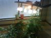
From the pic you can see this light does very well upside the south facing window, and I am using about 250w of power, with efficiency losses, to run this low heat, power company friendly light.

Oh yeah, the light is not finished in this photo, so, as I said, it will evolve.
 

Attachments

AlteredEgo

Active Member
Ok, I started commenting on some of the design thoughts, so I'll get more into the cost factor. It may differ for me, as I have tons of electrical, piping, and relays, capacitors, timers, etc from my HVACR + Solar business that I had to close when I became disabled (I prefer "medically retired") about 15 years ago.

I also have tools, meters, and a lot of scrap, that others may have to buy to duplicate this light, however I am going to try and explain the reasoning behind the design, so maybe you could accomplish the same thing with whatever you have or can find really cheap.

THE DISH/Reflector:

I decided on a reflector based on an old satellite TV dish. These have mounting hardware, adjustable mounting hardware already built to hold them in place, adjust angles, etc. These are cheap or free, just about anywhere, I am sure if you ask around, you can get one or more for free.

The part of the reflector I have yet to finish is a wrap around sheet metal skirt, flaring at 30-40 degrees from the edge of the dish, and attached to the dish with screws, welding, brazing, or pop rivets, whichever you have or can get.

Follow along, and you will see how I make a template and fabricate this reflector, which should allow ALL the light from these bulbs to be directed in about a 2' x 3' oval, minus what heat is dissipated by the big reflector. I may need to include a heat venting, probably passive convection flow, if I upgrade to a 400w HPS bulb/ballast, but I think the planned 150w will do just fine.

A note here, I planned a 150W HPS, but due to finances, and the babies screaming for lighting, I started with a 70W, which can be easily changed to 150, leaving me a 70W to use on other projects, possibly a second light.
 

AlteredEgo

Active Member
I went and got a 70W yard light @ Home Depot, and looked for lamp parts. I found nice little porcelain sockets, that mount with a single screw from inside the socket, but come with a metal arm with 3/8" lamp threads. They also had threaded tubing, and nuts that would fit the tubing, and hold the sockets, while passing the wiring through the tube to the back of the dish. These were 2.89 each, and a couple bucks for the threaded tubing, and a package of nuts.
Light_CFL Sockets-20110109-0229.jpg
I marked center line on the dish, in both directions, and then marked a symmetrical x over that. Than I marked each line, 3" from the edge of the dish toward center. This gave me a placing for 6 sockets for CFL's.
Light rear-20110108-2000.jpg
I debated on mounting/positioning of the HPS bulb, which, came with the yard light for $45 bucks. It has an aluminum housing, containing the ballast transformer, and starter, but no capacitor on this low wattage model. We will fix that as well then! It also came pre-wired to a socket on top that holds a photocell switch that turns it off in daytime. We don't need this, so I thought maybe I could take it out, and let ventilation flow out it. This would require cutting a hole in the center of the dish that is large enough to poke the light socket through.

After some thought, I decided I'd rather have the ballast remote, for weight consideration, and also I wanted to mount the bulb horizontally rather than vertically, the way it was in the factory assembly. I decided to use a cast aluminum light bulb socket the type used on motion sensor lights. I drilled a hole for half inch pipe threads, and mounted the socket so the bulb would be in the center of the dish. I gutted the whole ballast from the factory lamp head, and put it aside, after making a drawing of the wiring and colors of wires, so I knew what was hooked to what.
Light-hps socket-20110108-2031.jpg light-electrical box-20110108-2002.jpg
One note about the ballast and cooling it. The Manufactured UL Listed housing had no venting, no fins on the transformer, and rested right above the light. The only thing that cooled it at all, would be via the thin metal mounting bracket, heat sinking to the housing. You can add heat sinks to transformers to help them stay cool. If you are designing one for yourself, always remember to keep your ventilation/cooling at least as much, or much more than the factory design. I would not be surprised if you could not take a 70W transformer, and add cooling fins, and a fan, and POSSIBLY be able to run a 100w specialty bulb with it, maybe a MH, if you switch the starter out of the ballast circuit.

These ballast transformers are 120V, so they do not raise voltage or lower voltage much, but rather they soak up amperage when heavily loaded, and pass more through when lightly loaded, thus maintaining a reasonable amperage throughout the starting and run process of the HID bulb. These bulbs draw a heavy load on startup, and a much lighter load after the arc is started. The new digital ballasts use a type of transistor and sensing reactive circuits that do this same thing without an autotransformer. The ballast in a CFL bulb is like the digital ballasts. It is tiny because it does not use a transformer.

One of my reasons for building this light is efficiency, so after reading up on ballasts, I learned that a Power Factor capacitor is used in many models, with the result of greater efficiency, longer bulb life, and less heat on the ballast.

After gutting all the parts out, I found an old Computer Uninterruptible power supply. It was long since dead, probably just the battery, but who wants to buy one of those anyway, so it became my ballast case. You could use one of these, or any small box, as long as you remember to provide venting, and wire appropriate for the circuit protection, ie; don't use a tiny wire on a 15A circuit.

A breaker or fuse is designed to be the smallest "wire" in the circuit, and, in the case of a fuse, is placed in a case where it is safe for it to burn. Amperage produces heat! How much you say? OK, Amps X Volts = Watts, so if I have a 70W light, drawing say 95W due to efficiency losses, you can say that you have a total loss of about 25W in heat at least. A BTU (British Thermal Unit) relates directly to wattage. One watt = 3.41 BTU of heat, so 25W x 3.41 = 85.25 BTU's. A "Ton" of cooling is 12,000 BTU/hr, so you can get the idea that 85 BTU's is not a great amount of heat, but would burn/dry a leaf if too close. There are further losses of heat in the conversion of electrical energy to light, this is why the bulbs get warm.

Upon gutting the box, I saw that it has an IEC cord (think computer connector) socket, and a built in 5A breaker. I decided since I have only my 70W HPS @ about 95W draw, plus 6 26W CFL's for now, or 156W + 95W = 251W / 115v = 2.18A total draw. Great! I can upgrade this light to a total of about 550W and still be safe from blowing that 5A breaker. Be sure then, that any wire you use is large enough to carry much more than 5A, and you will be safe from fire as a result of a small wire becoming the fuse, and burning up in a not so safe place. There are places online to get this data, google for "amperage wire gauges", without the quotes, and you will find a million charts. OK, maybe a few thousand, but heck, one is all you need.

I also noted that the ballast is wired from the white wire, or neutral, to the bulb directly, and also one leg of the starter. This means the ballast transformer only effects the hot leg, or Black side of the 120v circuit, so I can use a common neutral for both the HPS and CFL's.

I really wanted a simple single cord, but one that would not be easily mistaken for a common plug and being hooked up to an inappropriate load, and looking through my stuff, I found a receptacle for a "Midwest" box. It is 20A capacity, and has 4 conductors, because an evaporative cooler motor has two speeds. I found a 12ft cord for this sort of proprietary plug and it has a green ground, a white neutral, a black hot, for high speed, and a red hot for low speed. I used the red for hot side of the ballast output to the HPS, and the black for hot side to the CFL circuit, and the neutral is common to both. Be sure and hook up the ground for safety! It goes to any screw on the cabinet, that is grounded all the way to the wall via the IEC cord.

I am tired now, so I think I'll lay here a bit, then go look at the babies, and stare at them telepathically telling them to make the good T for ME, LOL. Anyone else do that?

Next time, I'll get the box hooked up, maybe some more pics are in order here.

Later!
 

AlteredEgo

Active Member
kew seems good for one plant or a small sog
Yep, it is small, as I say I am trying for a 2ft x 3ft area, and later, with the sunlight I hope to cover a bathtub sized area, with a moving mechanism. I have always thought a moving light to be better, as no leaves can stay in the shade, so more of the available light is used by the plants. My focus on this project is to get decent production as inexpensively as possible, on a small scale, while having the ability to upgrade current equipment should decide on a slightly larger grow.

I am also working on a small basement space, where I will have to count on lighting totally, no sunlight available. I will try to develop solar power enough to run the lights, and will, of course use larger lights. I will likely stick with the moving lighting, multi-spectrum source idea, especially where I have no sunlight to help grow.

This reflector could hold one 400w HPS or MH, and 6-8 CFL's, however I would not want to go much over 42 watts each on the CFL's

Thanks for the comment, hope you check in sometime.
 

AlteredEgo

Active Member
Ok, lets see, when I last posted I was talking about the 4 wire plug and cord. The UPS box had a plug in it, standard duplex outlet, so I removed it, and removed enough metal to put the round NEMA 14-20P outlet. I left the little gaps around it where the duplex had been, to allow a little more air flow. The place where I removed the PC card left a small din switch hole, and a 9 pin serial cable hole, so this just adds to the ventilation.

I tied the contact of the plug that goes to the white wire to the neutral on the IEC plug, which also ties to the ballast start switch. I also put a 1/4" spade connector so I could plug in the capacitor later, on this white or Neutral wire. (When I kill the light again, I'll take the cover off, and take a few pics.) I turn it off with sundown tonight, so the babies can go to sleep, and make daddy some big buds.

The box already had a ground from the IEC connector to the chassis, so I connected a wire from the ground screw on the plug to that same screw. Oh yeah, you should use common colors on even internal wiring, if for no other reason, you won't forget what you have hooked up, and touch a green or white wire thinking it is ground, only to find it is hot due to some error.

Green - Ground
White - Neutral
Black - Hot
Red - Hot
Blue - Hot

There are more, and industries differ in color coding, but these are commonly accepted in national electrical codes.

Anyway, I located the black and red pins on the plug, and connected straight to the black from the incoming black wire, now connected to the 7.5 MFD (Microfarad) 370v capacitor. That one is so oversized for the job it is doing, it should never fail, but I have several more if it does. You can find these at refrigeration suppliers, and on old A/C equipment. The way the cap is wired from hot to neutral, it serves as a power factor capacitor for not only the HPS ballast, but also the CFL Bulbs. This should reduce the total power consumed by all the lights, but at least for sure the HPS.

On the red plug pin, I connected the output from the ballast transformer.

I plan to later connect the switch on the UPS case to main power incoming, plus it has an LED in it I can use to show some status, power or otherwise. I have thought about getting a panel mount digital timer, and cutting a hole for it to mount in this case, as I have loads of room left. I also will put on a piece of steel tubing, removed from the dish, on top of the transformer, with heat sink compound, to help keep the trans cooler. I even thought about installing a 2" computer fan on this tubing to pull air through it, but that would require either a 120v tiny fan, or a 12v supply also in the case. Either is feasible, but I'd have to order a 2" 120v fan I guess. I may have a 12v fan, and lots of 12v wall warts I could tear apart and hook up to power the fan. Passive airflow, over a heat sink, will be a bunch more than the manufacturer provided, so I should be running real cool.

I also thought about installing a relay, designed to turn the system on and off with a low voltage (24v) control signal. I'll likely talk more about this later, I'm already confused enough for now, lol.
 

AlteredEgo

Active Member
Great DIY Project Altered Ego ,,,
Thanks Donnybrook!

I am continuing soon and posting the current progress. I have shaped the wrap around hood for the reflector, lol this thing is getting pretty big. I am looking for a little hour runtime meter, to put in the ballast, so I can watch the bulbs usage. For now, I'll be happy to get some sheet aluminum to get this hood finished. Thanks for checking in, and do look back. I may become totally obsessed with this thing, adding thermometer for hood temp, fans to toss the weeds around, and who knows?
 

AlteredEgo

Active Member
Before I get into the next part of this, I wanted to mention that I do have a plan to recess the CFL bulb sockets into a 2" pvc coupling, with a cap to hold the light socket. I will set these so the CFL coils are the only part of the bulb that is exposed on the face of the reflector. I believe that when using such low wattage lighting, it is imperative to take every step to assure effective distribution, so I am not close to finished with the reflector, but it is coming along, and meanwhile I am using and testing it on real buds.
 
Top