Exhaust Ducting

Rusty Shakelford

Well-Known Member
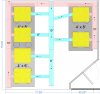
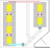
Hello Everyone,, I am in the process of up-scaling our Mother room, and I am at the point of figuring out the best way to connect the lighting for exhaust. We will be sealing the room and running (6) 400 watt MH. Of course I had planned on stringing them all together in the usual fashion, but did not think with this type of run, that it would be very efficient, so I am thinking a Trunk and Branch Setup instead.

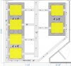
I have attached a simple diagram in hopes of getting some Experienced feedback on how efficient this setup would be. Am I missing Anything? Should the Intake be Bigger? and I reducing OK? Any Ideas? Suggestions?

Let me know what you think :)
exhaust.jpg
 

Nizza

Well-Known Member
i would do it like this instead, but spaced a bit different . sorry the cut and paste work is very sloppy
 

Rusty Shakelford

Well-Known Member
I have to imagine 14" is gonna be a bit much, I would like it to match the 12" return, but not sure its overly necessary, although reducing it down to 10" or 8" in the middle, to get to the end of the run might work very well.
 

SnapsProvolone

Well-Known Member
Thing is a 12" centrifugal blower is rated greater than 12" duct. To match a trunk to the fan, step up is required. In order to maintain velocity, plan to use a reduction in trunk size as distance increases and/or takeoffs are installed.

The intake air trunk should follow similar sizing.

A wye takeoff will be more efficient than a saddle / bullnose.

Ridgid metal with duct mastic is the way to go.
 

Rusty Shakelford

Well-Known Member
I think I have a little more of an efficient layout with this one. A MUCH Shorter Feed Line with a LOT less points of back pressure.. What do you think?
exhaust2.jpg
 

bird mcbride

Well-Known Member
This is a plantpot grow? With what medium? I'm guessing by your drawings, four plants per 400? Is this a veg room?
 

legallyflying

Well-Known Member
Ok, get ready for the piss on the pared post. That isn't going to work. Period.

There are a bunch of reasons but the biggest ones are friction loss and lack of the ability to regulate flow.

Your going to loose A LOT of CFM by using T's. Also, the first couple stubs off your main feed are going to see the majority of your flow and the last ones are going to see next to none.

Trust me, I have tried this kind of setup before and you need flapper valves at each hood to regulate flow and they are expensive!!

I showed your diagram to my buddy that is a union sheet metal worker (industrial HVAC) and he said "lol, ummm no) and walked away.

If your inlet and outlet have to be on the same wall then you want to have them running in the same direction.

My buddy said, one large off the shelf rectangle duct from inlet to the other side of the room. Like a 10 x 12. Then T it into the same size duct running perpendicular to the direction of the hoods.

Following?

Now, rotate all your hoods 90 degrees. Then 6" fans mounted in the T duct, one for each row. The row with more hoods is a straight shot to the outlet. The two hood row curves around and T's into the exhaust with a 45 degree union, NOT a 90.

That 45 degree union would be 6 x 6 x 8'. 8" being the part that goes through the wall.

Cleaner, much more efficient and cheaper.

I mean right not you have the air that goes through each hood taking two 90 degree bends... That's a no no.
 

bird mcbride

Well-Known Member
I do six moms planted in a row suspended in hydrorock with eight, four foot daylight tubes about 300 watts total. Heat is not an issue and if the snips get to close to the tubes it doesn't burn them like other lighting does.
In this same area where the tubes go vertical and horizontal a 150 watt mercury vapour MH hid is moved to where it is most needed when needed.
This is done in a 6'x1'x8" drip trough with timed dripped watering. Each mom is equipped with its own drip valve. If one fails she'll get what she needs from the drip of the others until I get there and fix it.
 

legallyflying

Well-Known Member
^ ummm that's great but what does that do to solve his HVAC questions?

I don't keep mothers at all. Take shit loads of labelled and numbered clones before flower, cull the poor performing ones, veg the ones that are doing well.

Problem solved.

If I had a warehouse I would keep moms but I don't. Kind of a harsh post on Mother's Day ;)
 

Rusty Shakelford

Well-Known Member
Ok, get ready for the piss on the pared post. That isn't going to work. Period.

There are a bunch of reasons but the biggest ones are friction loss and lack of the ability to regulate flow.

Your going to loose A LOT of CFM by using T's. Also, the first couple stubs off your main feed are going to see the majority of your flow and the last ones are going to see next to none.

Trust me, I have tried this kind of setup before and you need flapper valves at each hood to regulate flow and they are expensive!!

I showed your diagram to my buddy that is a union sheet metal worker (industrial HVAC) and he said "lol, ummm no) and walked away.

If your inlet and outlet have to be on the same wall then you want to have them running in the same direction.

My buddy said, one large off the shelf rectangle duct from inlet to the other side of the room. Like a 10 x 12. Then T it into the same size duct running perpendicular to the direction of the hoods.

Following?

Now, rotate all your hoods 90 degrees. Then 6" fans mounted in the T duct, one for each row. The row with more hoods is a straight shot to the outlet. The two hood row curves around and T's into the exhaust with a 45 degree union, NOT a 90.

That 45 degree union would be 6 x 6 x 8'. 8" being the part that goes through the wall.

Cleaner, much more efficient and cheaper.

I mean right not you have the air that goes through each hood taking two 90 degree bends... That's a no no.
Thanks for the input,, I am trying to sit down and figure out how your write up lays out, but I am not able to get the picture,, any way to do a quick layout or more detailed description of your posting?
 

legallyflying

Well-Known Member
Ummmm let's see here

The inlet is a rectangle duct that goes all the way across the room (parallel) to your hoods and then T's into the same size duct which will run wall to wall perpendicular to your hoods. (At the far end of your room).

Your basically carrying the cool air to the other side of the room with the rectangle ducting (you can find calculators online for CFM and size)

Then you mount your inline fans directly into the square duct and blow the cold air through each run of hoods. A 6" fan for both runs.

The run with more hoods wil exhaust straight out the wall. The run with the other hoods will Y into this pipe, downstream of the last hood.
 

Rusty Shakelford

Well-Known Member
Okay, then it is, what I was thinking it was. You dont think the 2 inline fans will compete for the Inlet Air? That will basically be (2) 400CFM fans giving us a little over 800CFM when all is said and done. I understand using round will be more efficient than using square ducting??
 

kief13

Well-Known Member
Would love to see a follow up report and pics of how the setup is working if you decide to use this,as I'm now contiplating switching mine around like this seems very simple and effective
 

Rusty Shakelford

Well-Known Member
YES, I will take pics of the project as it happens. Construction starts at the end of the month, HVAC will get installed at the beginning of June and the ducting will get installed right after.
 
Top