factorygrows
New Member
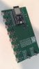
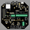
Looks like there is a few of us working on these! This is the V1 and we are just working on a separate dosing station for ph/ec/temp and pumps along with embedded ESP32 etc.
NiiiiceView attachment 5373491
Looks like there is a few of us working on these! This is the V1 and we are just working on a separate dosing station for ph/ec/temp and pumps along with embedded ESP32 etc.
The core of the PWM circuit is this:before i try stuff with my fan (not easy to get here in EU) i would like to get some more infos about the pinout and the needed signals to control the fan motor.
the board from factorygrows looks very simple. esp board with pwm moduls connected to the gpios?
could you share some infos about your wiring please?
would like to create a pcb on my own, but just for one usb-c connection (i have just one motor to control)
before i create and order a pcb, i would like to test the basic functions with stuff i have here, but for this, i would like to ask for your knowledge about the motor control.
like what pwm frequences are you using for the "original" steps 1-10 from the controller 69 pro. or did you measure them ?
thanks a lot and great work here")
Sweet! I can't wait to see how this turns out!I just ordered some unpopulated PCBs. Hopefully I didn't introduce a mistake while revamping the schematics!
View attachment 5375390
View attachment 5375391
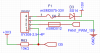
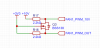
Thank you very much.The core of the PWM circuit is this:
View attachment 5375398
View attachment 5375399
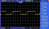
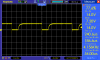
where FAN1_PWM_OUT is the output from the ESP32's pwm going though a level shifter. the 10V is taken from the fan itself (the wires are typically documented inside of the fan's control box cover). Also note here that I32 is connected to the fan's tachometer output which needs to be pulled up. I am using 4156Hz as the frequency for the PWM output and it is working perfectly.
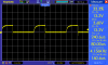
I guess I'll have to do my own measurements on the original controller then to confirm what I am getting. Operating at 4156Hz worked so far, but now I want to confirm. I have some good equipment, so this shouldn't be an issue.Thank you very much.
I found some infos where they say its ~5khz -> https://ledgardener.com/forum/viewtopic.php?t=6700&start=10
Also some interesting infos there
I wouldn't be able to tell for sure. The one I am controlling is a S4, but I suspect that it would work with all models having the following controlerAny restrictions on which version of AC Infinity inline fans this would work with? IIRC there have been 4, 2 DC & EC.
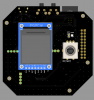
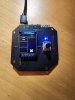
Ha, that looks absolutely wild. The boards have come out beautifully though! The sensor logging is definitely a nice tough. Are you using the rotary to navigate the interface?I could not resist the urge to cook more boards!
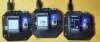
You are seeing the 2 units on the left running a modified lvgl demo. I was using it to test that the rotary knob and displays were working as expected. The one on the right is running my esphome config, albeit without any sensor which makes the screen look rather empty.
View attachment 5378056
In the lvgl demo (2 boards on the left), rotary control is used to navigate. But my original thought is to use it to increase/decrease the speed of the fan or toggle powerHa, that looks absolutely wild. The boards have come out beautifully though! The sensor logging is definitely a nice tough. Are you using the rotary to navigate the interface?
I don't know why you couldn't use it for both and use an encoder with a push detent as well.In the lvgl demo (2 boards on the left), rotary control is used to navigate. But my original thought is to use it to increase/decrease the speed of the fan or toggle power
From there, what you do is up to your imagination. That being said, I'm more and more leaning towards coding a project outside of esphome. If it was just for me, I'd go for a native esp-idf project since I'm very familiar with the environment, but I might also go with the Arduino framework. It does add a massive amount of bloat and can be frustrating to work with, but it's more accessible to a broader audience I think.I don't know why you couldn't use it for both and use an encoder with a push detent as well.
Mmmm... That's excellent to hear. Clicky encoders are always a great time. Can't wait to get my mitts on one of these, ha.From there, what you do is up to your imagination. That being said, I'm more and more leaning towards coding a project outside of esphome. If it was just for me, I'd go for a native esp-idf project since I'm very familiar with the environment, but I might also go with the Arduino framework. It does add a massive amount of bloat and can be frustrating to work with, but it's more accessible to a broader audience I think.
Nonetheless, you are right; the UI could be built with lvgl and speed control could be supported as a slider. Something to think about.
Oh and the button there is a rotary encoder with push button, so a good clicking feeling and no limits on number of turns