stardustsailor
Well-Known Member
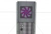
DJ SET -style grow light !!!!
LOL !!!!
Yeap !
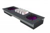
Double module growlight ,using Guod's framework style ....
But let's begin ....
First stage : ....
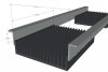
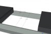
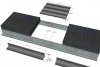
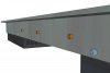
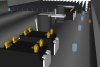
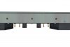
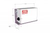
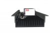
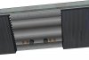
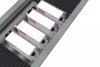
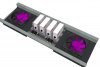
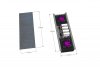
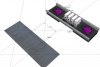
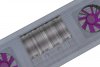
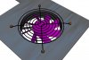
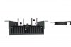
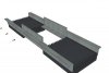
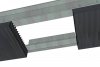
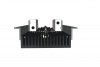
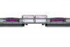
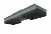
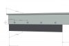
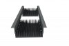
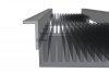
Building the basic frame ....
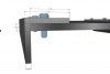
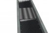
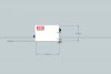
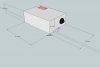
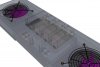
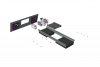
-2 x large heatsinks ( here used 200 x 160 x 40 mm
-2 x pcs of unequal angles (here used 2 x ~ 60 cm EN 10056-1 STD: RSA 40 x 20 x 4 ( mm ) of Alum 6063 )
- Alum Rivets ( here used 16 x pieces of 4 x 16 mm )
-Thermoconductive glue (cheap one-silicon based - will do ... )
........
 ..
..
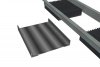
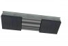
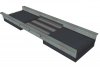
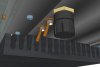
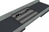
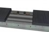
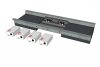
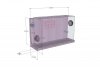
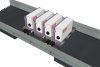
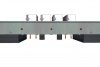
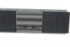
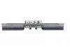
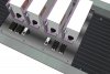
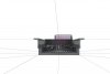
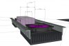
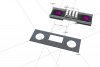
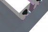
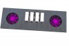
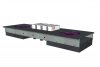
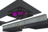
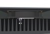
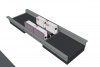
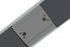
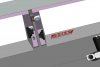
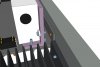
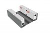
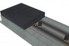
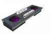
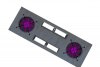
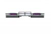
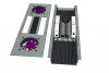
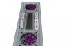
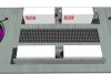
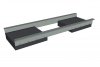
-Thermoconductive glue( silicone based ) is applied to the overlapping surfaces of riveted parts of heatsinks and angles ...
-Rivets can have ( A2 / A4 inox ) small washers behind ,for extra "grip " ...
LOL !!!!
Yeap !
Double module growlight ,using Guod's framework style ....
But let's begin ....
First stage : ....
Building the basic frame ....
-2 x large heatsinks ( here used 200 x 160 x 40 mm
-2 x pcs of unequal angles (here used 2 x ~ 60 cm EN 10056-1 STD: RSA 40 x 20 x 4 ( mm ) of Alum 6063 )
- Alum Rivets ( here used 16 x pieces of 4 x 16 mm )
-Thermoconductive glue (cheap one-silicon based - will do ... )
........
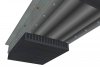
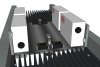
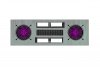
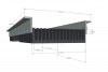
..-Thermoconductive glue( silicone based ) is applied to the overlapping surfaces of riveted parts of heatsinks and angles ...
-Rivets can have ( A2 / A4 inox ) small washers behind ,for extra "grip " ...