New Experimental Advanced DIY Designs.

stardustsailor

Well-Known Member
100 Watts of just WW !

I think it will work fine enough ....

(as long as the phosphor blend is ok .....
Ask about it ..
e-mail them ...
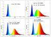
Ask for custom order ...2500-2700 K ...
The warmer the better ...

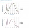
green+red phosphors ,not " broad yellow/amber..
That will make the whole "difference" ....
..
Trust me ...)

100 Watt array ,still remains an 'issue' ,to me ....

I'd would 've preferred 2 x 50 ..or 4 x 25 ....( Me ! )

Much more "relaxed" environment ,"deep inside " there ,in those hypothetic arrays ....


PS/ Edit :
If you're gonna contact them ,ask if possible for multi nm blue dies ..
Not all of them to be of the same range i.e 460-470 nm ...
Ask for some 440-450 nm and/or 450-460 nm inside the array ...
I.e 40 x 460-470 , 30 x 440-450 & 30 x 450-460 ....

There's a possibility that is doable without extra charges ...
Just ask ...
You don't have anythin' to loose ,by askin' ...
 

Bumping Spheda

Well-Known Member
I feel you. I've bought a 50W Warm White and a 20W Neutral White for my veg room. Decided to go easy on my CPU coolers 'cause I don't know their limitations. Better safe than sorry. I've emailed the manufacturer of my active heat sink asking for thermal resistances at their fans designed rpm's. Their technical page is... lacking.

As for the custom LED panels I asked my "supplier" what they were capable of. They have a 2395k blend, but that was measured with single wl Blues. They are willing to selectively coat the dice with phosphor, however, he said they'd have to charge a hefty fee so I decided against it. I'm thinking out of 100 dice:
45 x 440nm
45 x 460nm
10 x 660nm
"2395k" phosphor over everything, even the Red. I'm hoping efficiency on the 660's won't be hurt too much doing this.
60USD for 45mil die, 30USD for 35mil die
25USD shipping

Expensive? Yes. Worth it? Yet to be seen. Cheaper than a Kessil, at least I can look at it that way.
 

stardustsailor

Well-Known Member
2395 °K ?

....That is warm enough ..!!!

(Can they go so low at warm white ? )

definately good for testing out ...

....
Now ...

"2395k" phosphor over everything, even the Red. I'm hoping efficiency on the 660's won't be hurt too much doing this.


Already there's plenty of 660 nm light at the WW phosphor blends (lower than 3000 K ) ..

Asian 660 nm dies are really "spikey " ....

Phosphor average 50% Diameter ,if way small (<10&#956;m ) ,can have an impact on red light from red leds ...
( not enough "channeling " for red light ,through particle voids .... )


I'd go for .....
45 x 440nm
45 x 460nm
10 x 645 nm
 

stardustsailor

Well-Known Member
There's something not right there ....

It can't be a warm white with the blue spike at R.Power at 100% and at same time at ~ 600nm,also have 100% r.Power .. (broad amber/yellow phosphor there ......)...

Something is not right ....

No...This Warm White phosphor blend ,I'm afraid ,it's a common Warm White "mix" from "Azia " ...
Will it work ?
Of course !
It will grow plants just fine ....

But ,comparing to WW leds with Red+green phosphor mix (i.e Oslons 2700 K or intematix RP 2700 K ) ,they
are "poor " ,regarding spectral quality ...

Which also means that ,quality WW leds ,must kick some serious @$$ ,there ...
Given that ,they are also more efficient power-wise ....

But it is worth giving a try ...

Although expensive ....85$ ....(45 mil+ship)


Consider building a smaller array ,but of better quality leds ( or even blue quality leds with RP screen ) ?

With ~ amount of $ ?

Maybe something is doable there ....

Search a bit more ....
Don't get in a hurry to spend ...
 

Bumping Spheda

Well-Known Member

stardustsailor

Well-Known Member
Hey!
You've found yourshelf a nice mixing chamber there !!!

OOOOhhh!!!!
Now ,you're talking ....
Go for the RP !!!

At least you will have a quality cooling system , really effective WW RP screen
and an aluminium "mixing chamber "solution until maybe something better pops-up ....

You can always change the array underneath ...(if you wish so in the future ) ....

Throw out the reds..
Replace them with blues ...
Intematix RP 2700 K RP screen has more than enough reds ...
" Feed " (excite) the screen ,instead ,with more blue leds
Or keep just 4-6 pcs of reds ....
( 50% 645nm , 50% 660 nm seems quite nice ratio ...)


100Watts ,hybrid combo of B/R leds ,2700 K Remote Phosphor screen,aluminium reflector (with lens if wished )
and "CPU heatpipe tech "active heatsink .....

Not bad !!!!!

Way.... Experimental & Advanced...


Only for the brave ....

(still I insist ...Go lower on power ...100 seem much ...)
 

Bumping Spheda

Well-Known Member
The only problem is they told me that these LED's run 10 rows of chips in series, 10 rows in parallel, and because of that they need dice of only the same voltage and current draw in any given "row." This is why I decided on a 10% Red spectral balance.

I think I'll just bite the bullet and have a little more Red than may be required. It should still be a damn good spectral distribution, imho. Not to mention I'll have ~90W of supplemental LED's hanging near-vertically around the tent. So ~185W, give or take, on a single plant, hopefully very little training, just some trimming here and there as she goes.

Thanks for steerin' the boat a bit for me, sailor. Much appreciated. :bigjoint:

Edit - Yikes, I saw your edit on the last post. I'll have to ask them what their policy is on 50W LED's. If it throws the spectrum off too much (way too much Red, or none at all) I might stick with 100W just because. We'll see.

Edit 2 - And there's these guys. Idk what gives, they've got "20W" LED's that are running 16W. I'll have to ask my guy if they can under drive a few chips to achieve the correct spectral balance.
 

stardustsailor

Well-Known Member
For edit 2 of yours :

Look at their chromatic CIE coordinates of array ( the cross at scheme of their developer software pic )
Look then at post #25
 

stardustsailor

Well-Known Member
Cromalit :
chromalit spectra.jpgchromalit  color coordinates.jpg


Oslon :
WW color groups.JPGoslon warm.jpg

And overlaping to compare directly :

chromalit  vs Oslon WW ssl  both at 2700 K.jpg

Black line :Oslon SSL WW 2700 K
Green line :Chromalit RP 2700 K

!!!!!
Almost same ! ( Green + red phosphor high CRI* Warm white led light .... )

Oslon has a tad (just a tad.... ) more green phosphor or it has peak at a shorter wl of greens ...
While Chromalit has a tad more "deep red " peak than oslon ssl (+ ~ 10 nm =>` peak at 640-650 nm for chromalit RP )


Chromalit 2700 K coordinates :

Cy =0.4101
Cx= 0.4578


overlap  coordinates.jpg

Well it seems it " falls" somewhere between V7 ,V6 ,W6 & W7 of oslon ssl 2700 K groups .......

Edit :


* High CRI Warm White leds ,are "easy " to distinguish from other WW leds :

-First ...Of course they are labeled "high CRI " . > 90%

-Second : They have always that little "bump ",somewhere in green/yellow wls ,at their R.Power spectral curve ..
It's the green phosphor peak ,"faded" / "flatened " away ,from both directions ..
From blue die emission and from red phosphor emission ....


-Third: The "longer" wl the red peak(phosphor) has( >620 nm,up to ~670 nm ) ,
the more increased CRI ..


I.e ( totally random example )
With the same die and same green phosphor ..
A led with 630 red phosphor peak will have ... 90% CRI (Color Rendering Index )
With 640 = 93% ..(say ..)
With 650 =95% ..
With 660 =97% ..
and so on ...
(up to ~670 -680 nm ...after that limit ...reds become .."invisible " .....
CRI decreases way dramatically ..)

....but regarding photometric power (lumens ) ,WW of high CRI have decreased values,to the rest of white leds ....
'Cause of less "visible" deep red peak and more FR radiation(no lumens there ..not visible light ..) ..

So less lumens for high CRI WW leds ..


Although radiometric power of light stays -roughly-about the same with the rest of white leds ....
So do not get confused and think that Warm White leds ,are of ( ...way... )less output power..

It's only your eyes that're foolin' you .....
Green plant(s) "see" WW led light , otherwise ....
Way ...'yum-Yummy'(complete-full ) and powerful enough ! )

Edit 2 :
As for human vision use ....
Warm white leds are used as more "relaxed " light and where color rendition & "reproduction " has to be accurate ..
(Museums,art galleries,shops,boutiques ,ect ....)

While for strong and powerful illumination (with poor color rendition,though ) cool whites are used ..
(stadiums,street lights,automobiles ,industrial outdoor areas ,harbors,ect )

Neutral whites ,are something in between , to "bridge" ,those two sides ....
 

guod

Well-Known Member
Sorry to beat my drum here, but I think a bit of clarification is needed
View attachment 2491460


Arrangement of NW & WW using analog clock for visual:

NW at top and bottom of vertical stack (12 & 6 o'clock) with possibility of 730 in the center (maybe on a separate switch).

WW on each side at 2, 4, 8 and 10 o’clock

Additional clusters will employ existing diodes of first cluster to create their shape,

this allows for bars, or square panels

If 3w diodes were used then each cluster would be 21w; and 5w would be 35w

But if going to RP covers then Merkaba may not be necessary, although.....
..........

makaba.jpg
 

stardustsailor

Well-Known Member
Ok ....
Light has 3 basic "colors "

"Basic" means that they reproduce all the other colors by mixing between them ,while can not be "made " by any other color mixed ....

Where color= light Wavelength ..
Those colors are Red -Green -Blue ...( The known RGB ....)

All together make white light ....
None of them ...is black ...Absence of light
("black" is not a color or a "wavelength " ...Is pure ..nothin' ...)

Now ..

R+G = Yellow
G+B=Cyan
B+R= Magenta
....

(not for paint....Only for light ...) ...


Yellow +blue=white
Red+Cyan =White
Green+ Magenta (violet )= white

Modern white leds use mainly first combo ,to reproduce white light ...

A blue die which excites a yellow phosphor .....(broad-peak ) ..

Older white led tech ,was using three dies ....
A red ,a green and a blue one ....
Output light was .."false white" ...
3 sharp spectral curve peaks at B,G & R ,"blended " only at lower values of R.Power ...
Kinda like a "fork " ......
RGB white leds ...Not so good for plant growing ...
Warm White Leds ( CRI 70-80 )
Example of blue die at 455 nm and a broadpeak yellow phosphor ...( flat peak at ~ 578-582 nm )
ww with yellow broadpeak phosphor.jpg

3 points represent the "peaks " of die and broad-peak yellow phosphor ...
Green lines are the temperature limits for " warm white light "
Shaded area is theoritically possible hues of WW ,that can be achieved by this method ....
Whole area enclosed by the "big triangle" is all the wls ,"contained" in this warm white light ....
(Way roughly ...It doesn't work exactly with "peak-points" and straight lines connecting them ..)

A typical WW led of this method will have a spectral graph that looks like :


A "broad" peak at yellow-orange wls ( 570-600 nm ) ......
Smooth-"sloping down " at both sides .....
Blue light is way less ,thus light appears "warm" (yellowish /amber hue )
But ....
Reds over 620-630 nm are not in much of R.Power ...
Given that our vision ,"weakens" at that red area ....
Red objects illuminated with this led ,will not appear at their exact hue .....
CRI=70%


High CRI Warm Leds

Now ...
Yellow is not a "basic " color .....
It is "made " from red + green ......

What about a led that instead of a yellow phosphor has a red and a green one ,together ?
high cri ww with R_G  phosphor.jpg

Way wider "palette " there .....

But also "triangle " is way of larger area....
All the hues inside the "triangle" ( " peak " points of blue chip & r/g phosphors ) ,are contained
in this new type of Warm white light..
Much more "complete" regarding r.powers of different wls ....
Specially at red area ......

Spectral curve of these leds ,has always a "bump " somewhere in green/yellow range ..
And red peak is past ( > ) the 610-620 nm "mark" ....

....
No need to be mention the -quite big- spectral quality difference between those two types of WW leds ....

And since the low CRI type ,grows plants just fine ....
One can imagine the capabilities/possibilities with the other type ,of high CRI ....
 

stardustsailor

Well-Known Member
Guod ,why so rich in FR 730 nm ?
Pet ,it won't work that way (probably ) ....
Way too much FR ...
Unpredictable outcome there ....( i.e streching or severe Shade avoidance syndrome ..)
 

guod

Well-Known Member
Guod ,why so rich in FR 730 nm ?

not my way, but pet ask for it
red/farred ratio is way of for always on

--------------------------

Is it any possible way ,utilising a dimmable driver ,
to have a " multipositional " rotary switch ,so to select
Pre-adjusted Current ?
I.e .

0= off
1=350mA
2=400mA
3=450mA
4=500mA

that is very simple

dimm-sw.jpg
 

PetFlora

Well-Known Member
^ Actually, I suggested FR as it seems SDS seems to favor some.

I believe NW (or WW depending on whose diodes) will do just fine, although a pinch of NW in the center of an otherwise all WW can't hurt- or maybe a CW
 

stardustsailor

Well-Known Member
Actually, I suggested FR as it seems SDS seems to favor some.

I've just suggested that some FR leds should be used along with "harsh "(powerful) 640-670nm light ..
Just to balance the Phy,by counteracting phy action of R - FR .

Also ,given the large amount of RL ,FR leds can have an "boost " effect on PS ,due to R-FR light Emerson effect ,this time ..
Not to be used with NW or WW leds ,though as both have adequate amounts of FR light (if in great numbers/power ) ...
 

stardustsailor

Well-Known Member
Guod ,why so rich in FR 730 nm ?

not my way, but pet ask for it
red/farred ratio is way of for always on

--------------------------

Is it any possible way ,utilising a dimmable driver ,
to have a " multipositional " rotary switch ,so to select
Pre-adjusted Current ?
I.e .

0= off
1=350mA
2=400mA
3=450mA
4=500mA

that is very simple

View attachment 2493079


Whitey "things" are resistors ,isn't that so ?
Yes ...
So to calculate ..
x A current of dimming circuit
10 V = max output current of driver
5 V = 1/2 of max output current ..

So if 10 v = i.e 600 mA
then 5 V = 300 mA

R=V/ I

For max current 600m A =>R[SUB]600mA[/SUB]= O ohm
For 300m A => R[SUB]300mA[/SUB]= 5/x


Hmm...
So for 350mA ..

350/600 *10 = 5,8333 V

R[SUB]350mA[/SUB]= 5,8333/ x

And so on to find the rest ...

Ok ....The dimming circuit needs max=10 V ....
Have to know it's current x so to calculate the resistors to be used ...

Correct ,Guod ?

Or there's another way also to calculate the resistor values ?
 

PetFlora

Well-Known Member
SDS, As you well know, you think out loud (in writing) making it hard to follow when you jump around between actinics and simple NW WW CW. I'm a KISS minded guy.

How about CW in the centers, athough I think an amplifying crystal would be best
 
Top