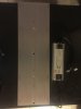
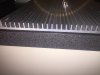
I ended up accidentally breaking the hinge off, didnt take much pressure though ... the internals seemed to show to me that it seems a blob of solder is preventing the 'gates' from moving ... even with needlenose plyers they werent moving ... I ordered a soldering iron last week so should be here this week, so maybe hopefully i can 'dab' it to let the wire in.
I'll email Meijui about this problem - apart from this issue i'm happy so far (delivered quick, well packaged, genuine lm561c's, full 'kit' with everything required, solderless DIY, good tech support). I still have the 3000k flower board waiting for hookup also, so I'll test that next
[update] just tried the other board, the exact same problem in the exact same spot

will await Meijiu email. Their tech support has so far actually been pretty good for the most part