Reflow soldering XP-E and XP-G3 to mcpcbs

NaturalFarmer

Well-Known Member
61kgQz4XGTL._SL1500_.jpg

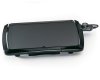
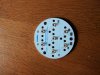
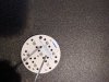
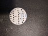
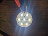
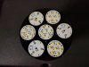
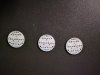
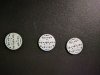
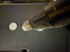
Using a $20 Presto electric griddle and a heat gun I tried this tonight for the first time using 7 emitter MCPCBs from this site.
http://led-mounting-bases.com/en/led-mcpcb/16806-mcpcb-diametre-40mm-pour-7-led-cree-xp-g3-compatible-optiques-khatod.html
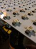
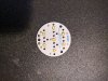
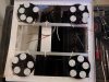
I put the solder paste on all the pads and both contacts. I then warmed up the griddle slightly and put the emitters (4000k and 660 photo reds) on with the + going the correct way and then turned on the griddle to 400 degrees. I screwed up a few times and had to reheat again to remelt the solder and turn a few emitters but it got easier to lay it right as I went on. The first few times, I didn't warm the griddle first and was having a tough time placing the emitters correctly without bumping off target (room temp paste would have helped).
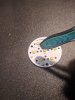
The solder paste will begin to look dry just before it melts. Once it does just push down slightly on the dome of the emitters and pop out any excess solder. The emitter will skate back over to the contact if you move it off. Wick the solder beads and there you have it.

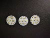
Definitely a little nervous doing this the first time, but it really was easier then I thought it would be and was pretty fun. Now to start on the Osram Oslons.

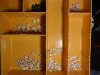
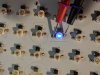
Not the prettiest but not bad for a couple hours and a few bowls. I experimented with a few of the three emitter XP-Es to see how long I could keep it on with the emitters. Left it for twenty minutes (you can see the discoloration) and it still lit up.
Anyways hope some enjoys this, I would recommend giving it a shot.


IMG_20170307_010020.jpg

https://www.amazon.com/Presto-07047-Touch-Electric-Griddle/dp/B0051XSIO6
 

Attachments

NaturalFarmer

Well-Known Member
This was a youtube video from a DIY flashlight guy that helped me, but it really seems to be mostly trial and error and gaining experience with heat transfer of the mcpcbs and gripping the emitters with the right tool (which I don't have yet) and putting the proper amount of paste on.
 

NaturalFarmer

Well-Known Member
After doing this a few times, even a fat fingered fellow like myself could do this without too much stress on the emitter. I didn't keep the air gun too close but the silicon seemed to be able to handle it when I did try. I did lose one dome, but only because of my clumsy tweezers or operator error dropped it wrong side up on the hot plate.
 

NaturalFarmer

Well-Known Member
The Osram oslons blues 450nm were much more difficult than the far red 730nm or hyper reds 660nm for various reasons to get good contacts. People should really try this though if they have interest but are nervous, it is way too fucking easy.

I have found the best way is to paint a small amount of paste on the contacts (when the board is warm/hot) and wait until the solder wets before putting on the emitters. You have time, so don't get nervous when doing it. If you leave the PCBs on the hot plate but turn it off when the solder wets, this gives you enough time to place the emitters before the solder cools down. These 7 emitter pcbs have test contacts on all emitters so it is fairly easy to figure out if you mounted one of the emitters backwards, and when I do I just mark it with a pencil and reheat the board until the solder flows again and I can switch it. A few more and I should be able to start mounting on the heatsinks.
IMG_20170312_093836.jpg
 

Boatguy

Well-Known Member
Never thought to do this on a multichip pcb.
Been eyeballing some opulent north america modules but im betting it would be much cheaper doing it this way.
 

NaturalFarmer

Well-Known Member
The Meodex MCPCBs from the link above were free shipping with a $200 order. I think they can customize boards as well. Really decent pricing and quality IMO.
 

NaturalFarmer

Well-Known Member
Deconstructing the Blackdog and reworking the emitters with solder paste and a heat gun underneath ( you can see the emitter three deep that is circled is sitting high because the solder hasn't melted yet. The light came with two halves like this board shown and I have taken off the Epistar UV and IR diodes along with their white/yellows and green diodes on both. Replacing the whites with XP-G3s at 4000k and CD bin 3500k 3590s on this light spread.

The 6 or 8 IR emitters are trash unless I get an Iguana ( what were they thinking?).....but I am gong to put the UV on their own driver by themselves so I can switch it on/off and put it on a timer.


IMG_20170314_013759.jpg
 

Attachments

Last edited:

welight

Well-Known Member
Hi Natural Farmer
your a quick study, nice work, if your interested in higher performance 7 up boards, check our TPAD, in both Copper and Alum, these are Direct thermal path, this means the dielectric has been removed from under the thermal pad of the led, on the PCB, meaning your heat transfers directly to the Heatsink with no dielectric impediment, dielectrics typically have a high % of fibreglass so they restrict the PCB performance when running at higher currents. The boards can be series or individually addressable if you want to add multiple colours

Cheers
Mark
 

NaturalFarmer

Well-Known Member
I wanted to show the easiest method that I have found. I take the blank MCPCB and heat it up to 400 degrees and apply a dab of solder paste on the contacts using the tip of a syringe(which will begin to melt almost right away and even out), then switch off the power when the solder tins (the paste will tin at around 400). The next step, I place the emitters on correctly and then reheat back to 400 degrees. Give the emitters a small tap on the dome to eject any excess solder.
This method allows the emitters the least amount of time on the heat.

I did three of the 7 emitter boards in 12 minutes I think.
Using the Osram Oslon 80 in 5700k for these ones.


IMG_20170323_133409.jpg
IMG_20170323_133452.jpg IMG_20170323_134006.jpg
IMG_20170323_140123.jpg

IMG_20170323_134415.jpg
 
Last edited:

CannaBruh

Well-Known Member
A toaster oven (better with some microprocessor modifications for a nice control over the heating/cooling profile) works very well. For those diodes and for such a small pcb and one offs I would just as quick hand solder. Practice on some scrap pcbs.

My congratulations on the skillet re-flow, it really is kitchen science (pun intended)
 

NaturalFarmer

Well-Known Member
I would prefer to heat from the bottom up (I believe the emitters agree) and no soldering would not be easier by any means...sorry

Can you solder 21 emitters in 12 minutes and make a pot of coffee? I doubt I can.

Solder paste is the shit. These emitters were on the heat for less than a minute per board.
 
Last edited:

CannaBruh

Well-Known Member
Wasn't intending to sound overly critical, only offering another option to someone who might have an oven vs a skillet lying around.

Toaster ovens conventionally have elements both top and bottom and would fulfill your underside preheat parameter.

Coffee should have been the first thing you did in the morning, and while it's brewing I'd hope you can solder more than one diode in 30 seconds.

Just to reiterate, nice job!! bongsmilie
 

NaturalFarmer

Well-Known Member
Using the Blackdog shell, I mounted four 140 mm pin fins with 35 emitters each. Three engines with Osram Oslon 80's mostly in 5700k but a few 660nm and even less 450nm which are being driven with a Meanwell HLG-185H-700A (Drove 17 but I dropped it down to 15 for obvious reasons) and the other using one of the cheap blackdog driver at 900 ma power was only able to drive the weaker 660nm with a punch. Sill working on this but almost there, I need thermal adhesive because I bought the wrong shit last time and also need to finish securing the heatsinks with a couple bars and finishing wiring it. Too bad I got into this light shit after wasting a couple G's on hogwash.
IMG_20170402_115221.jpg


For the bigger build I used an aluminum door frame from the 70's (works like a charm my friends but I imagine windows as well). I gutted the Blackdog and separated the two PCBs and heatsinks with CXB-3590s in between. I also took out their emitters in white, IR and UV as well as green. I think 5 of the 6 UV diodes were dead or became dead after the extra heat I hit them with. Ill post some pictures of that a different day. Driving the 3590's at 2100ma so its cranking the white but I probably screwed that up.
 
Top