Seems like one big problem, I really could use some help!
- Thread starter Dnl.svrr
- Start date
Dnl.svrr
Active Member
FFFFFFFFFFFFFFFFFFFFFFFFFFFFFFFFFFFFFFFFFFFFFFFFF-
Just bypassed one led (The fourth one) and all the other seventeen leds went up and bright, so bright I've got a thousand floating points in my field of view now.
God damn.
Two hours and a headache later... and it's probbl just faulty wiring. I say that cause the led does lit up when tested individually.
Won't touch it for now, though. I'm tired of this. Tomorrow. Ahahahahaha
Thank you so much!


Dnl.svrr
Active Member

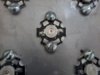
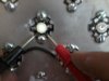
Well, this is the crude workaround I used.
Gotta say they look bright for 1-watters (I know this doesn't mean anything concrete, but they do seem brighter than the ones in the UFOs I've seen)
The pic was taken using my cellphone, so all kinds of artifacts show on the lights.
Thanks again!
Dnl.svrr
Active Member
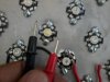
I just realized I made a terrible mistake and 4 leds are burnt because of that. None of them were bad in the first place, the thing is:
All the poles in the star are able to conduct power! Even if there's one ledchip (as opposed to rgb leds p.ex), ALL the other 4 poles bring power to the diode in the core. When I bolted them down, the bolt head made a connection between negative and positive poles creating a short in some diodes. Since the bolt is also connected to the aluminum tray I'm using for a chassis, it created some nasty interference.
I just wish I'd thought about that before.
What is the solution? Do I have to isolate the bolt heads from the poles in the star or just rotate the star in a way the bolts connect equal polarities?
Dnl.svrr
Active Member
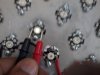
So, basically, all the 90 leds are shorted by design. Hahahaha
That was really stupid, in hindsight. I might use some silvertape on the edges to isolate them, should that do?
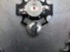
Btw, this illustrates what I'm saying:
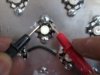
Unpowered, directly on the led "legs" (middle pair), upper pair, lower pair.
The bolt was lifted on this one eliminating the short.
patrikantonius
Active Member
You should redesign your attach so that the bolt is not in contact with the connectors. You could use insulating soft washers for instance.

Dnl.svrr
Active Member
How well would hot glue perform as an insulator? What about insulating tape? It's been hard to find plastic covers that fit the bolts I'm using.
Thank you all for your comment and advice, I have 90 more leds on the way and waiting to buy the final 36 or so. Hopefully I'll have a box of light with 2 top and 4 side lamps.
I kinda feel lucky for only having 5 burnt diodes after shorting, well, 90.
Thank you all for your comment and advice, I have 90 more leds on the way and waiting to buy the final 36 or so. Hopefully I'll have a box of light with 2 top and 4 side lamps.
I kinda feel lucky for only having 5 burnt diodes after shorting, well, 90.
Eraserhead
Well-Known Member
Sounds like you did everything correctly, as far as things that wouldn't cause things you are experiencing goes.
Did you make sure the -/+ is connected properly on the stars? Not your connection, but the connection from the LED to the star made by where you bought it from.
To test it, reverse your -/+ where your problem LEDs are and see what happens.
Did you make sure the -/+ is connected properly on the stars? Not your connection, but the connection from the LED to the star made by where you bought it from.
To test it, reverse your -/+ where your problem LEDs are and see what happens.
Dnl.svrr
Active Member
Eraserhead, they all test normally using the multimeter now. I've lifted all the bolts, they bolt heads were actually the problem. They're too big, so when I bolted the stars down the bolt head closed the circuit between the connectors on the edge of the stars, shorting most of the 90 leds. I'm currently deciding whether I should use thermoconductive glue (seems the easy and best way around) and keep the bolts to attach some massive heatsinks or keep the bolts and use some kind of insulation. (Not likely - I'm not fond of working with the bolts given the practicity of using thermoconductive glue (way easier to insulate properly) and might use thermoconductive glue from so on for the other panels. So since I'm changing anyway, might as well redesign from the start.)
Thanks for your comment!
Thanks for your comment!
Eraserhead
Well-Known Member
Yeah, you want to make sure your connections aren't conducting to the heat sink.
In my experience, see if you can find some plastic or non-conductive washers, they'll break the circuit for sure. Just as long as the soldering isn't too sloppy.
Those glues are a mess.
In my experience, see if you can find some plastic or non-conductive washers, they'll break the circuit for sure. Just as long as the soldering isn't too sloppy.
Those glues are a mess.
Rasser
Active Member
Using screws to attach the star pcb's is not a bad idea I think,
when using the right flat headed screw and non conducting washer.
www.Mousers.com Nylon washers selection. I would think a M3 would be appropriate.
when using the right flat headed screw and non conducting washer.
www.Mousers.com Nylon washers selection. I would think a M3 would be appropriate.
Dnl.svrr
Active Member
Since I'm going to build other sources in this project, I'd like to keep it standardized. So I'm leaning towards thermoconductive glue.
It's been a pain to find (I live in a small city), but I've found some DIY articles with tests showing similar performance to arctic silver adhesive while using only regular thermal paste and araldite (2 centigrade difference over 1h using the exact same gear). Might head that way, but I haven't decided yet. Anyone tried this before?
By the way, any information on how to test a driver using the multimeter? I'm afraid I could've fried it due to that short, am I correct?
Thanks again, eveyone!
Rasser
Active Member
Dont know about glue, but the 3x1W PCB star-heatsink from a emergency sign i got,Since I'm going to build other sources in this project, I'd like to keep it standardized. So I'm leaning towards thermoconductive glue.
It's been a pain to find (I live in a small city), but I've found some DIY articles with tests showing similar performance to arctic silver adhesive while using only regular thermal paste and araldite (2 centigrade difference over 1h using the exact same gear). Might head that way, but I haven't decided yet. Anyone tried this before?
By the way, any information on how to test a driver using the multimeter? I'm afraid I could've fried it due to that short, am I correct?
Thanks again, eveyone!
is fitted with a square double side thermo conducting tape patch, the size of the pcb star
that is very sticky, and can be reused if the LED needs replacing.
The best way to test the driver is when using a dummy load, without it then the driver will max out and maybe pulses or shutdown, or just keep the voltage at the maximum possible.
whats the info on the driver ?