That's neat. Is that with 1 strip tested or 4 in parallel and the image might suggest?I received some updates from Teknik today and have attached the latest goniometer reports for the strips for you to look at.
Testing Growlight Australia Gen 3 strips (and maybe side by side?)
- Thread starter Rocket Soul
- Start date
Grow Lights Australia
Well-Known Member
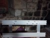
The numbers are in. At about 1.05A or 50W (53W from the wall) I am getting a temperature reading of 55C at the hottest point in the middle out to 51C at each end and 53C along the edges of the 60x13 T-slot. The ambient temperature is 33C so the differential is about 22-23C. Once you build a frame I would expect these temperatures to fall a little because of the extra aluminium in the frame that will help sink the heat. I measured in nil wind so there was nothing blowing over the T-slot to cool it. I also let the strip warm up for over an hour but maximum temperature was reached in about 5 minutes so it didn't make much difference. I would say that is pretty much as hot as they are going to get unless your grow room is over 35C and you have no fans blowing.
OK I decided to blow a fan over the strip to simulate a small to moderate amount of air movement in a tent and the temperature dropped down to 37C within a minute which was +5C over ambient. I would suggest you are good go if you want to use the recommended T-slot.
OK I decided to blow a fan over the strip to simulate a small to moderate amount of air movement in a tent and the temperature dropped down to 37C within a minute which was +5C over ambient. I would suggest you are good go if you want to use the recommended T-slot.
Grow Lights Australia
Well-Known Member
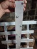
That is just a single strip at various currents. The photo is only for reference.That's neat. Is that with 1 strip tested or 4 in parallel and the image might suggest?
Rocket Soul
Well-Known Member
Fantastic on both answers. Ill reassess those t-slots with my grow buddy, makes fan placement a bit easier since we would normally try to get it in between light and cannopy. An in any case will run on lower watts in my grow.The numbers are in. At about 1.05A or 50W (53W from the wall) I am getting a temperature reading of 55C at the hottest point in the middle out to 51C at each end and 53C along the edges of the 60x13 T-slot. The ambient temperature is 33C so the differential is about 22-23C. Once you build a frame I would expect these temperatures to fall a little because of the extra aluminium in the frame that will help sink the heat. I measured in nil wind so there was nothing blowing over the T-slot to cool it. I also let the strip warm up for over an hour but maximum temperature was reached in about 5 minutes so it didn't make much difference. I would say that is pretty much as hot as they are going to get unless your grow room is over 35C and you have no fans blowing.
OK I decided to blow a fan over the strip to simulate a small to moderate amount of air movement in a tent and the temperature dropped down to 37C within a minute which was +5C over ambient. I would suggest you are good go if you want to use the recommended T-slot.
Thank you for the Lux conversion! The conversion of the phone app I use (used) reads 15-20% low and my plants were not happy!Hi Rocket Soul I received some updates from Teknik today and have attached the latest goniometer reports for the strips for you to look at. The Lux to Lumen conversion is about x0.021 but it changes slightly depending on the current which affects the colour temperature a small amount.
I got the machined T-slot back last week so I am going to do some temperature readings on the mounted strips at 50W and let you know shortly. It is a warm day today and the ambient temperature is about 35C.
View attachment 5347724
View attachment 5347727
View attachment 5347725
Considering the spectrum, is a lux meter a better option for these lights rather than the current PAR meters?
Prawn Connery
Well-Known Member
Lux is never a better option than PAR because PAR will always read true and lux changes wth colour temperature, which itself changes when you increase or decrese the current, as some LEDs perform better than others during current change, so this slightly alters the spectrum.Thank you for the Lux conversion! The conversion of the phone app I use (used) reads 15-20% low and my plants were not happy!
Considering the spectrum, is a lux meter a better option for these lights rather than the current PAR meters?
Lux meters are only really good as a point of reference when you are using the same lights. You find out where your plants are happy, and then try to maintain that lux reading.
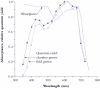
On the subject of PAR, I have mentioned this before: unless you are using one of the newer ePAR meters that also measures far red light (400-750nm), our lights will always pump out about 10% more PAR than the meter reading.
This is because there is obviously 10% far red in our lights that doesn't get read by a typical 400-700nm PAR meter, but also because there is photosynthetic light below 400nm. I really don't know why the cut-off point is 400nm when the action curve goes well under 400nm to as low as 350nm. Have a look at the McCree Curve and tell me photosynthesis ends at 400nm! This is why I like those 405nm Nichia diodes and UVA in general – just look at all the photosynthetic action your plant is missing using a typical 450nm blue pump LED light. It's a good 20%
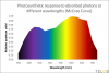
So if a typical plant likes 900 PPFD, then you would want 800 PPFD under our lights. It's all about reading the plant.
It's a methodoligal "flaw" in the data. The McCree curves were recorded with plants that were grown under artificial/greenhouse light. It contained no UV so the plants had no protective pigments that would decrease quantum yield. There is also data for UV adapted plants where the response falls off more steeply.I really don't know why the cut-off point is 400nm when the action curve goes well under 400nm to as low as 350nm.
Rocket Soul
Well-Known Member
Came up short of recycle boards on our veg remodel so i thru up this quick and dirty number to see how these veg aswell. The flower build will be more slick, had to use what we had at hand and hand fitted. It hangs over one of our last veg trays, towards flower. 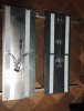
Prawn Connery
Well-Known Member
Good info. I did find some more recent tests comparing outdoor to indoor grown absorbance and quantum yield, and you are right. However, outdoor grown plants still photosynthesise below 400nm.It's a methodoligal "flaw" in the data. The McCree curves were recorded with plants that were grown under artificial/greenhouse light. It contained no UV so the plants had no protective pigments that would decrease quantum yield. There is also data for UV adapted plants where the response falls off more steeply.
What is also interesting is how plants grown without UVB respond. I haven't been able to find any research on the matter, but it would be interesting to see what the action spectra is for plants that have been exposed to high UVA (380-400nm) and not UVB (<310nm).
My guess is it would be somewhere in-between, as UVB drives the UVR8 response much more strongly than UVA.
1.2.2 - Chlorophyll absorption and photosynthetic action spectra | Plants in Action
[[{"fid":"167","view_mode":"figure_right","fields":{"format":"figure_right","field_file_image_alt_text[und][0][value]":"","field_file_image_title_text[und][0][value]":"","field_caption[und][0][value]":"%3Cp%3E%3Cstrong%3EFigure%201.8%3C%2Fstrong%3E%20Upper%20curves%3A%20Diethylether%20solutions%2...
Rocket Soul
Well-Known Member
Got alu profiles and t-slot done, ready to build and flipp after new years as i will be away over xmas. The plants in veg are a bit bigger than what we would like usually but should be a good run. Strain is rainbow chip. Next flipp after that will be animal cakes and hopefully some new interesting genetics partly by @nachooo
Rocket Soul
Well-Known Member
As far as veg these strips seems to do the trick, we get good growth and plants under these strips always seem to have the best look to them; nice green, allways praying the hardest and you can almost see some plants on the next tray turning a bit towards them. 150w over one tray is working fine but our veg runs a bit slower (on purpose) than most other grows.Came up short of recycle boards on our veg remodel so i thru up this quick and dirty number to see how these veg aswell. The flower build will be more slick, had to use what we had at hand and hand fitted. It hangs over one of our last veg trays, towards flower. View attachment 5348789
Will update with the main build a little later.
Rocket Soul
Well-Known Member
The strip build was very easy and enjoyable but under some time constraint, i didnt get too many photos.
Ill give some build notes:
Each strips is 48 cm or about 4/5 of 2 feet. Im using 8 strips to light an area of about 4.5' x 2ft using a MW HLG320-48B as power source.
I sized the fixture to 120cm/4ft wide but it can be adjusted. The way i figure sizing is that i figure i can count on the 2 most exterior strips will shed half their power on the area not directly under the fixture. So if i subtract 1 strips power from its max output i get a decent indication on how much power is available directly under the light. In my case i get about 35w per square foot considering my light basically being a 4x2.
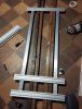
We built the light by first putting together the structure or frame. The way we usually work is somewhat ocd triggering but very convenient and imo works better. Rather than marking out holes then drilling pieces separately we do a handfitted approach; we put down our T-profiles upside down between square wooden brs which hold them in place, then just fit the most exterior two profiles on top, one person drills, the other one holds down the t-slot profile and drops a screw when you have a clear hole thru both of them. You drill thru the groove, so you have the face side of the tslot forward.
https://www.item24.com/en-be/profile-6-60x12-light-natural-45165 link
Repeat for next hole and then secure the screws nuts. Used M3 here.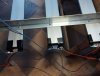
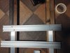
Heres some finished pics of this detail. Each t-slot connects to the t profile with 2 screws, on this pic second screw on the other side of the t.
After the exterior 2 you have a frame and can then just measure out your strip placement one strip at a time and secure them.
I was somewhat worried that this approach wouldnt work, that the grooves of the t-slot wouldnt be able to fit both the screw heads in the groove but i was happily surprised; it fits fine with the m4 screws we had to use to find the right size trays, about 12mm.
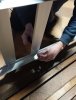
But actually this was not my first approach to get the strips on the profile. It was this dipshit idea:
Thinking i should fit the strips on to the screws when actually the just slide in: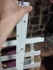
You have to be a bit careful cause the screwheads and trays, they can get messed up, but basically just slides in there. Marvelous and so much easier than my initial stupid idea, lol
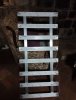

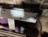
Heres the light with all strips in place.
After that its just wiring up. The wires are long enough to get 3 strips into one wago, or any other connection. I went with double ended strips so its easy to series if you prefer.
Finally we made some holes and loops for hanging, secured the unused wiring in inside the t-slot and used some endcaps and tape for securing them.
It was definitely a quick build, and very satisfying. When i look at some of the other lights ive made, with the mess of cables for far red, uv or massive amount of strips on soft its so refreshing to have a really clean looking light with very little cabling yet full range.
Hoping to thread the next test run.")
Ill give some build notes:
Each strips is 48 cm or about 4/5 of 2 feet. Im using 8 strips to light an area of about 4.5' x 2ft using a MW HLG320-48B as power source.
I sized the fixture to 120cm/4ft wide but it can be adjusted. The way i figure sizing is that i figure i can count on the 2 most exterior strips will shed half their power on the area not directly under the fixture. So if i subtract 1 strips power from its max output i get a decent indication on how much power is available directly under the light. In my case i get about 35w per square foot considering my light basically being a 4x2.
We built the light by first putting together the structure or frame. The way we usually work is somewhat ocd triggering but very convenient and imo works better. Rather than marking out holes then drilling pieces separately we do a handfitted approach; we put down our T-profiles upside down between square wooden brs which hold them in place, then just fit the most exterior two profiles on top, one person drills, the other one holds down the t-slot profile and drops a screw when you have a clear hole thru both of them. You drill thru the groove, so you have the face side of the tslot forward.
https://www.item24.com/en-be/profile-6-60x12-light-natural-45165 link
Repeat for next hole and then secure the screws nuts. Used M3 here.
Heres some finished pics of this detail. Each t-slot connects to the t profile with 2 screws, on this pic second screw on the other side of the t.
After the exterior 2 you have a frame and can then just measure out your strip placement one strip at a time and secure them.
I was somewhat worried that this approach wouldnt work, that the grooves of the t-slot wouldnt be able to fit both the screw heads in the groove but i was happily surprised; it fits fine with the m4 screws we had to use to find the right size trays, about 12mm.
But actually this was not my first approach to get the strips on the profile. It was this dipshit idea:
Thinking i should fit the strips on to the screws when actually the just slide in:
You have to be a bit careful cause the screwheads and trays, they can get messed up, but basically just slides in there. Marvelous and so much easier than my initial stupid idea, lol
Heres the light with all strips in place.
After that its just wiring up. The wires are long enough to get 3 strips into one wago, or any other connection. I went with double ended strips so its easy to series if you prefer.
Finally we made some holes and loops for hanging, secured the unused wiring in inside the t-slot and used some endcaps and tape for securing them.
It was definitely a quick build, and very satisfying. When i look at some of the other lights ive made, with the mess of cables for far red, uv or massive amount of strips on soft its so refreshing to have a really clean looking light with very little cabling yet full range.
Hoping to thread the next test run.
Rocket Soul
Well-Known Member
I was offered some strips to test. Also we grow in an open space which means we dont have reflective walls. High wattage boards doesnt really work well in our space it uses too much light to light the walls. We try for 20-30cm hanging height.I guess someone has to ask this. But why get strips and not a long board or two?
cobshopgrow
Well-Known Member
nice build mate, keep posting.
for the nuts, there are normally t slot nuts one can buy, several types.
one looks like this.
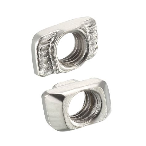
for the nuts, there are normally t slot nuts one can buy, several types.
one looks like this.
Rocket Soul
Well-Known Member
I knew i had some more photos somewhere:
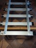
Setting up the frame with the heatsinks. So happy i could get it done thru the grooves/rails rather than using angle at the sides.
Tightening nuts and bolts; side poaition seems the easiest.
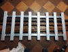
And finally full frame.
Another advice (unless i already commented on this): if youre siliconing those solder pads its best to wait until the light is finished; working with semi dry silicone on the strips was no joy.
All in all i wanna underline how easy this build was in comparison to what im used to. Between top quality diodes and the ease of putting together this is a nobrainer to me. All in all i think its a somewhat pricey strip but generally worth it. It helps a bit if you can source cheap t-slot, maybe in alibaba, and it gives you the possibility to build a light for yourself with super slick and professional look, which has everything you need: spectrum, efficiency, high quality sealing, fits in 1m tents, 48V driver.
Setting up the frame with the heatsinks. So happy i could get it done thru the grooves/rails rather than using angle at the sides.
Tightening nuts and bolts; side poaition seems the easiest.
And finally full frame.
Another advice (unless i already commented on this): if youre siliconing those solder pads its best to wait until the light is finished; working with semi dry silicone on the strips was no joy.
All in all i wanna underline how easy this build was in comparison to what im used to. Between top quality diodes and the ease of putting together this is a nobrainer to me. All in all i think its a somewhat pricey strip but generally worth it. It helps a bit if you can source cheap t-slot, maybe in alibaba, and it gives you the possibility to build a light for yourself with super slick and professional look, which has everything you need: spectrum, efficiency, high quality sealing, fits in 1m tents, 48V driver.
Attachments
-
 5.4 MB Views: 4
Prawn Connery
Well-Known Member
I know why you had a hard time fitting the strips to the T-slot – because you mounted them on the wrong side! Hahaha! The flat side is the mounting side to ensure maximum metal-to-metal contact for heat-sinking. The slots on the back act as the heatsink fins to dissipate heat.
And yes, the holes in the strips were designed to line up with the middle of each slot, which is the thinnest part for drilling and tapping. It also allows you to do what you did with the T-slot nuts/screws.
Apart from that, looking good!
And yes, the holes in the strips were designed to line up with the middle of each slot, which is the thinnest part for drilling and tapping. It also allows you to do what you did with the T-slot nuts/screws.
Apart from that, looking good!
Rocket Soul
Well-Known Member
Oh, i seriously thought the t-slot adaptation was for doing away with drilling. Ill check how hot things get when were at full power just in case when i get up to see the grow next. Glad to see you still postingI know why you had a hard time fitting the strips to the T-slot – because you mounted them on the wrong side! Hahaha! The flat side is the mounting side to ensure maximum metal-to-metal contact for heat-sinking. The slots on the back act as the heatsink fins to dissipate heat.
And yes, the holes in the strips were designed to line up with the middle of each slot, which is the thinnest part for drilling and tapping. It also allows you to do what you did with the T-slot nuts/screws.
Apart from that, looking good!