cxa3070s@350mA orientation

purplegrower02

Well-Known Member
If tapping a blind hole measure the depth with a caliper"vernier" and transfer to the tap and wrap the tap with masking tape so you literally can't go to deep. Saved a lot of taps that way. And if your buying a hand tap look into A RATCHET handle. Believe me your forearm will thank you.
 

stardustsailor

Well-Known Member
I know!! I had no issues gettin them mounted/soldered in place- but they would just beep at me when I tested them. Made sure the anode/cathode was on the right side and all. Used a skillet on my stove to do it. (Couldn't get em to heat up enough with the solder gun like the luxeons) killed me... REALLY wanna be able to use those XPEs.

Couple possible reasons of 'mishappens' :

-Not good aligned solder paste with the pads ...

-Too much solder paste.

-Bad solder stencil.

-'Steep' heating up or 'steep' ramping down ..

-leds 'moved' / 'shaked' before solder solidified ..

-bad mcpcb ( shorted pads and/or shorted with pad's core ).

-too soft / low temp solder paste alloy.
 

MrFlux

Well-Known Member
Some sweet ass #s 12 and 18" away, but I am alarmed by the max draw (about 40 watts more than i figured it'd be, 272w) but dims down right to 119w (with fans [+8w]) anyone care to lay some insight of what I could have done wrong?
If you're running at a lower voltage than the maximum of the driver, it will supply more than the 700mA you may have used in your power calculation. Also remember the driver losses.
 

Scotch089

Well-Known Member
If you're running at a lower voltage than the maximum of the driver, it will supply more than the 700mA you may have used in your power calculation. Also remember the driver losses.
So should I just adjust my drivers till I am to my desired ~230w with a killawatt meter and I can assume I'm at 700mA and running the emitters (specifically the reds) safely?
 

stardustsailor

Well-Known Member
Theres no 'linear current regulator' on a switching constant current power supply .

A "sensing' circuit measures the 'load' (resistance) of the output .
Then it varies a 'switching' (pwm) circuit at the AC side ,so the incoming current will meet the set criteria/level/adjustment ..
Of course this is done by varying the output voltage .
But the actual 'voltage pwm regualation ' is done on the HV AC side ...

(AC and DC sides are connected at the actual power rail with a small transformer and at the sensing part with optocoupler(s)-usually....

Cheers.
 
Last edited:

stardustsailor

Well-Known Member
Thank you.

so... what's in that block? :P (OLP)

I tried to rip mine apart when I got it, but I couldn't get it apart.
Block =certain circuit ,assigned to a certain 'job' ,part of a 'bigger' circuit ..
I.e ...the OLP ' block' of a CC Led driver ...
:P

Check here ,the pdf's ...


Edit:
" Unconnected coils " ( :lol: LOL ) = the symbol of a transformer ....


circuit_symbols.png
 

SupraSPL

Well-Known Member
Scotch if they are beeping it could be excess solder under the pads. It helps to give them a slight push while they are cooling to squeeze out any excess solder. Also, did you put the iron on the side of the star where the aluminum is exposed, rather than the solder pad?

Yep the HLG will put out more than 700mA if the dimmer switch is at max, maybe as much as 770mA.

If you post a list of all the LEDs in the string I can put it in the spreadsheet to get the approx vf and power draw at 700mA.
 

Scotch089

Well-Known Member
Thank you guys. Yup it all makes sense now- I'll post my "spreadsheet" :P in a sec.

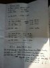
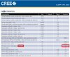
I did the math and @700mA I'd be around 230 led watts, + the 6% innefficinecy of the drivers comes to 27.6w, then +8 for the fans. So total about 265w, pretty damn close and makes me feel much better. I am guessing I'm over 700mA though supe- say 3-4% more would put out 7.7 more watts which would put me smack dab on 272w. Woop! So, if I really wanted I could nudge the pot down to 265w and be pretty spot on, eh? Think 3% extra current will hurt my luxeons/Crees? But I guess I don't know what they define as "max current" either.

Okay, numbers, sorry for the scribbles ask away if you can't read it.

image.jpg
 

Scotch089

Well-Known Member
And supe I did press the chips down when i reflowed them with my tweezers. Lotsss of solder out the side=== my culprit?

Let me know if your numbers match up with mine if you do decide to crunch em! Thanks brother! Again I couldn't have done this without you guys leading the way, my hat's off to all of you
 

epicfail

Well-Known Member
I am guessing I'm over 700mA though supe- say 3-4% more would put out 7.7 more watts which would put me smack dab on 272w. Woop! So, if I really wanted I could nudge the pot down to 265w and be pretty spot on, eh? Think 3% extra current will hurt my luxeons/Crees? But I guess I don't know what they define as "max current" either.
I think your over it with the Photo Red XPE's, I would run them softer.

xpe-spec.jpg

 
Last edited:

SupraSPL

Well-Known Member
So is it
(4) CXA3070s
(4) XML2
(6) Cree XP-E 630s
(5) Lux ES 660s

If so, the Vf of the string should be about 177 and dissipation should be about 124W. Driver losses would be about 10W.
 

stardustsailor

Well-Known Member

http://en.wikipedia.org/wiki/Transformer


Block diagram is a diagram of a system, in which the principal parts or functions are represented by blocks connected by lines, that show the relationships of the blocks. They are heavily used in the engineering world in hardware design, electronic design, software design, and process flow diagrams.

The block diagram is typically used for a higher level, less detailed description aimed more at understanding the overall concepts and less at understanding the details of implementation. Contrast this with the schematic diagram and layout diagram used in the electrical engineering world, where the schematic diagram shows the details of each electrical component and the layout diagram shows the details of physical construction. Because block diagrams are a visual language for describing actions in a complex system, it is possible to formalize them into a specialized programmable logic controller (PLC) programming language.

http://en.wikipedia.org/wiki/Block_diagram
 
Top