3IN1 Dimming Part II :A more advanced approach

AquariusPanta

Well-Known Member
Now ....

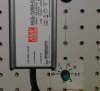
finished and installed new power adjust interface ...
With an 4N33 optocoupler ...
View attachment 3320522

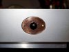
And also installed a RCA plug at rear of case ,for PWM input signal. (+5VDC )

View attachment 3320510

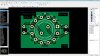
And completed the "AutoDia" device ,Arduino Uno based.
View attachment 3320511
With two parallel outputs ,able to drive two V series units.
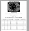

AutoDia device :
View attachment 3320512

SET:
At the center ,a 10 turn ,low tolerance (high precision)smooth linear operation pot ,the one with the flat screw head and golden screw -on cover ,adjust the fall/rise (half period ) time .
From 1 minute to 720 min (12 hours) ,in 'steps' of 1 min .

So,at 24 h full light regime ,the device will be increasing power for 12 hours and will decrease power for the other 12 hours.

At top right is the Max Power adjust pot .Single turn ,many-many small 'clicks' ,
adjusts max power "peak" from 55% up to full 100% ,in steps of 1% .(linear)

Bottom Right is the Min Power adjust pot.same as before , single turn ,many 'clicks' pot ,
adjusting min power "valley" from 10% up to 54% ,in steps of 1% .(linear)

An example of " Day " operation is : At veg of 18 hours ,it can increase power from say 20% atr hour 00:00 up to 60% at hour 09:00 ("Noon" ) .
And then it will decrease it gradually and linearly back to 20% ,at hour 18:00 .

At flowering ,it can be set ,to increase power for 6 hours ,say from 40% up to 100% and then for the rest 6 hours ,
to decrese from 100% back to 40% ...

Not something fancy ..(geolocation,season,multi-channel;s,etc ..)
But it was quickly made and it will do it's job ,just fine ,I may suppose ..

View attachment 3320514

Golden 'screw-on cover'is the 'case' from a cheap old rca wire plug .
It serves to avoid accidently turn the rise/fall time pot ,as it is quite sensitive in changing minutes .
The other two are 'locking' into their setting (res value) in every 'click' ,as they rotate


Cheers.
:peace:
Ever consider adding a handle to the case?...

It's all looking super dope as usual.

:clap:
 

salmonetin

Well-Known Member
...typhon way use pwm... i keep thinking on my crazy resistive way with reles+resistors.... yeah its not linear smooth like pwm... but dimming without pulse its atractive to me... no flickering way... ...but maybe its only other crazy idea mine...

...substitute the dimmnig pwm function with a resistor+rele function ...or maybe with a digital potenciometer function.... and you can go with substitutions and test with a lot of reef controllers codes .. maybe only other crazy idea mine...

,,,and typhon way dont go for certain drivers...you need add hardware... and maybe little changes on code... with reles + resistors we go with on off function for drivers with suport resistive way...

...typhon page said...

NOTE: Not compatible with MeanWell LPF and HLG LED drivers. ... i think dont go on HLPs too...

...typhon is an arduino + lcd 16 x 2 with botons + rtc...

...but heyy thanks for the link i see one manual, code and libraries... some to looking or read tonight...;)

...off course its not lazy stoner way... its more crazy stoned way...

saludos
 
Last edited:

Positivity

Well-Known Member
Hmmm...my typhon may not work then. Oh well...will see. Won't get a chance to try and hook it up for a bit. Strange it seems since I thought it was just working off a 10v signal
 

salmonetin

Well-Known Member
...bro Pos.... 0 -10 its pwm way too...or maybe im wrong... i dont say pwm way dont go...

...and what driver you used for your test with typhoon?...

...what typhon code you have or try... what version?... and think remember an special model of you... these model maybe use other code... or came in with preprogramed code...

...the code its for comparation with boostled... or other codes for typhoon...

...example... ...one comparation for diferent version for typhoon code... ...R15--R20 versions..;)

https://code.google.com/p/typhon-reef/source/diff?spec=svn20&r=20&format=side&path=/trunk/software/typhon/typhon.pde&old_path=/trunk/software/typhon/typhon.pde&old=15

...sorry to Sds for my offtopics posts...

saludos
 
Last edited:

bicit

Well-Known Member
Question @stardustsailor, have we addressed so called 'digipots' or digital potentiometers?

I'd like to be able to dim multiple drivers individually using arduino in order to soft start the lights in the 'morning' and fade at 'night'. As well as experimenting with dimming during power outages to extend the life of/reduce the number of backup batteries.

PWM dimming seems like the lowest hanging fruit, but you've discussed human health hazards associated with PWM dimmed light.

Any other approaches to dimming with micro controllers?
 

churchhaze

Well-Known Member
I should have read a bit further in. It's top advertising line was "Tired of turning knobs?". Nope. I don't have any knobs in my grow room, just lights.

If you can use it to replace your timers, that's great. Let me put some weed through my system before I continue posting. hehe :joint:
 

SupraSPL

Well-Known Member
Dimming by Resistor.
Design can be build with using only an appropriate potentiometer ,
or a more complicated approach of using a single pole rotary switch with multiple positions and the dedicated resistors (connected in series) .
Easy to build ,not much fuss .
Thing is that cheap potentiometers have rather large tolerances from the indicated resistance and
also dimming by a potentiometer is not the most 'linear ' dimming fuction ever .
A great addition would be any mean of measuring the driving current (Io ) ,thus a digital or analog amperemeter is rather a great addition ,but also more circuitry involved.
The rotary switch option,as it has 'preset' Io outputs ,won't benefit from a amperemeter really.
You know me, I usually take the lower tech approach. I though about adding an ammeter to the strings but I realize it consumes some power all the time, slightly lowering efficiency. So you can have it both ways by temporarily connecting a multimeter to check current and just mark it on the board where the dimmer is mounted.

Crude example
DSC08402b.jpg
 
Last edited:

churchhaze

Well-Known Member
You know me, I usually take the lower tech approach. I though about adding an ammeter to the strings but I realize it consumes some power all the time, slightly lowering efficiency. So you can have it both ways by temporarily connecting a multimeter to check current and just mark it on the board where the dimmer is mounted.

Crude example
View attachment 3421943
I think there are ammeters that work by wrapping it around a wire to check for magnetic flux. I'm not sure how much power that would save. I'm more worried about adding complexity than I am making minor improvements to efficiency, which is the reason I leave things like ammeters out of my designs.

"A designer knows he has achieved perfection not when there is nothing left to add, but when there is nothing left to take away." - Leonard Nimoy, Civilization 4. .. okay, actually Antoine de Saint-Exupery ..
 

Positivity

Well-Known Member
Just like there are beta fish bowl lovers and reef enthusiasts and everything in between. All kinds...:razz:

Taking everything extra away leaves the sun. Cobs are wonderful but they are not the sun...;)
 
Last edited:

stardustsailor

Well-Known Member
Any kind of human control of an electroniuc device,
is done via a "Human Interface Device " .
Along a visual ,auditoral or of both ,"feedback" is needed to the human controller / user .

Ammeters belong to visual feedback devices ..

Or it can be numbers of preselected positions of output power ( Io *Vo ) .

Like those two :

P5202819.JPG
^^^ from 300 mA to 2200 ma , in 12 pre-selected "steps*** .

P5202820.JPG

^^^ from ~ 380 mA to 1530 mA in 6 pre-selected steps .


***

HID.JPG

rot switch 1.JPG
^^^ N of drivers = 2 .For Io max ,then Rmax >= 100K / 2 >= 50K (or left open )


6pos switch.JPG
^^^ N of drivers = 4 .For Io max ,then Rmax >= 100K / 4 >= 25K (or left open )
But the rotary switch used is controlling 2x drivers per pole ,
thus R max >= 50K per pair of drivers ,(per switch pole also ...)


Cheers.
:peace:
 
Last edited:

salmonetin

Well-Known Member
....you can check amps without afect to propio consume....and the consume for these ammeters are independent with her self bateries...pinzo ammeters...

saludos
...im wrong ...im talking on measuring the AC side and Supra talking ...measuring on the DC side...

...info about Non-Invasive Current Measurement ...on AC side...

http://openenergymonitor.org/emon/buildingblocks ....in Non-Invasive Current Measurement Section... ..and other greats reads too...

...on DC side i saw voltmeters and ammeters (really an voltmeter reading through a shunt...) but you can power the ammeter and the voltmeter with independents baterie/s...

...one autonomous system for a ammeter and a voltmeter for DC side...
...in spanish... sorry...:P


...I like a lot the driver ZXY6005 for an diyer led lab... but i prefer the model D over the S model... and the ammeter and voltmeter autonomous with some modifications too (in my mind the ammeter and the voltmeter go on separate and independent bateries and the ammeter and the voltmeter are the 5 digits models ...) ...and a modificated ATX from pc...some recycling too.. my crapy mix way ;)

...or the 12010S model... ...for the high Vf on CXBs...

...ojala pueda comprarme un combo asi este año... maybe im only dreaming again...

...the links and vids are only for examples or ideas...

...thanks a lot to the vids author... eseeee Pabloooo... saludos de 99...

...si wilson... infusion time... and back to the cavern...

PD...thanks for your like Supra... i apreciate a lot....beware of electricity bro...

...safe first... maybe one diferential (only know the name in spanish sorry) with high sensivity 10 mA or 0.7 mA... to protect better the persons...

Saludos
 
Last edited:
Top