3IN1 Dimming Part II :A more advanced approach

stardustsailor

Well-Known Member
It seems that the 3IN1 dimming function is becoming rather a market's standard ,as it is incorporated by many other L.E.D. power supply manufacturers ,aside from MeanWell.

Every individual way of three ,has it's own pros and cons ,regarding the overall design and dimming function of the drivers .

In short :

Dimming by Resistor.
Design can be build with using only an appropriate potentiometer ,
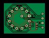
or a more complicated approach of using a single pole rotary switch with multiple positions and the dedicated resistors (connected in series) .
Easy to build ,not much fuss .
Thing is that cheap potentiometers have rather large tolerances from the indicated resistance and
also dimming by a potentiometer is not the most 'linear ' dimming fuction ever .
A great addition would be any mean of measuring the driving current (Io ) ,thus a digital or analog amperemeter is rather a great addition ,but also more circuitry involved.
The rotary switch option,as it has 'preset' Io outputs ,won't benefit from a amperemeter really.

Dimming By +10VDC external voltage .
It needs an external +10 VDC PSu ..What more to say ?
Dimming can be tricky and/or unstable ,depending on the external voltage source.
Needs Common Grounding of led driver's dimming circuit and the external voltage power source.

Dimming by Pulse Width Modulation (PWM ).
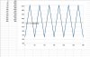
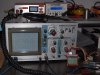
Needs a pwm signal of +10VDC ( usually of 100-3000 Hz frequency ).
" Dawn-noon-dusk " ," season " ," weather " and other things regarding the "light output-spectrum vs time " aspect of LED light automation can be simulated or performed,by the use of a digital controller (from aquarium led lights) or by a microcontroller like Arduino Uno .


More here => *Part I

Personally in my most recent lights ( V series ) ,the rotary position approach was favoured ,
because of it's simplicity in designing and building ,the low cost of the parts used & their operational durability and the fact that the preset Io outputs ,really serve fine the final purpose of dimming function.
That ,until recently ,when a special order came up from a customer ,that while he liked much the idea of the rotary switch manual power adjust ,he also wished for the automated control option .
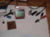
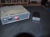
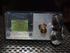
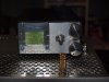
He asked for a small audio "jack" input ,at the rear side of the case,where he can plug an Arduino and do his things ....

I had to come up with a new human interface design .....

At first glance ,I saw two possible issues...
1) A switch should be installed to disable the manual rotary switch option and enable the PWM input ..
And vice-versa ..

2)A 10 VDC power supply had to be found ..Arduino outputs +5VDC signals ..
3IN1 dimming function of led drivers needs 10 VDC ...

I liked not the possibility of those issues becoming a reality..
Neither I like a switch at the rear of the case ..
Neither I like to use a 7810 IC to make +10VDC out of the fan power supply (+12 VDC ) ..

I had to come with something else ...

1) Why not use the last (#12 ) position of the rotary switch as the "Manual/Auto " setting and at the same time to be the max output ,when at "manual control " ?

2) Why not ,to use the drivers own +10 VDC output from DIm+,for the PWM signals from Arduino ?

Well ..Yes ..Why not ?

And here it is ..

new hid pwm.JPG

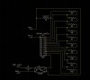
How it works ,on the next post ....
 
Last edited:

Abiqua

Well-Known Member
Wow, I actually understand this, which is saying something.

It also seems to be extremely practical! Always be condensing redundancy, is that the creed of an electrical engineer?

Could you use DIP switches in place of the rotary switch if running less resistors?
 
Last edited:

stardustsailor

Well-Known Member
How it works :

Rotary switch position #1 :
Current "enters" the circuit from "Dim+" input (connected to Dim+ wire/pin of the LED driver ),from there to switch pin A to switch pin 1 and goes through resistor R2 ("LowLimit" ) to Dim-
(connected to Dim- wire/pin of the LED driver ).According to the number of drivers used and LED/COB driven ,
an appropriate value of resistance should be chosen for the R2 ,for the wished lower(but still operational ) Io setting .
At V series lights ,which feature two drivers, a 6K8 resistance sets both drivers to output 300mA .

Rotary Switch positions #2- #11 :
Current "enters" the circuit goes through resistor R2 and the resistor R3,for position#2 .For position #3 current goes through resistor R2 and the resistor R3 and resistor R4.And so on.
At V series lights 10x 3K9 resistors are used .
39 K in total plus 6K8 the "LowLimit" one= 42K8 at switch position #11 . An Io output of ~2A .
For the max of 50K ( 100 K / 2 x drivers),7K2 are missing ....
Or ....

Rotary Switch Position #12 :
Well ..
Instead of 50 K ...
Drivers will also output their Io max when Dim+ & Dim - are left "Open" ..
Not connected .
So,Pin 12 (Dim,+) of rotary switch connects to an optocoupler's Collector pin ,
while Emitter pin connects directly to Dim- .
Now Dim- and Dim+ are not connected
(optocoupler's transistor= normally open ) .
At least until the optocoupler's led is energised .

If no pwm signals are triggering the optocoupler ,
the switch position #12 will set the Io at max.
At the same time it enables the PWM input .

So,the " If no pwm signal is inbound ,Io=max ." is known ..

Now ....
Pay attention here ,at this point ....
If an 100% duty cycle pwm signal is inbound .....
Then Io= 0 !!! .
(0% of Io max )

A 100% duty cycle pwm signal ,
means that Dim- ( optocoupler emitter ) and Dim+ (optocoupler collector ),
are connected .
( optocoupler transistor is closed ) .

Connected Dim + & Dim - wires/pins of led driver(s) means 0% of maximum Io .

So ,regarding the programming part ,
0% duty cycle of PWM signal means Io= max rated and100% PWM duty cycle means Io=0.
90% d.c. = 10% of Io max
10% d.c. = 90% of Io max ...

And so on ...

The 1K resistor (can be any value from 250 to 1K ),is there to limit the current at the optoisolators led .Protecting both the tiny FR led inside the optocoupler and the Arduino's PWM output pin ,from frying (overcurrent might occur if no resistor R1 is set ).

Optoisolator used , is a simple 4N33 ,but many-many other types can be used also ...
 
Last edited:

Abiqua

Well-Known Member
Forgive my ignorance but what is your max A, that you are running?
Is this fixture, also powered with the HLP[HLN?] 42v drivers? Why do they show a max of 1.9a? [HLP's]

May seem off topic, don't mean to clutter, but I have been eyeballing these drivers ever since the 1st build with them and now that you doing realworld calcs with them, I am that much more fascinated.

Again thanks for your sharing, invaluable :peace:
 

stardustsailor

Well-Known Member
Forgive my ignorance but what is your max A, that you are running?
Is this fixture, also powered with the HLP[HLN?] 42v drivers? Why do they show a max of 1.9a? [HLP's]

May seem off topic, don't mean to clutter, but I have been eyeballing these drivers ever since the 1st build with them and now that you doing realworld calcs with them, I am that much more fascinated.

Again thanks for your sharing, invaluable :peace:

The 1.95 A is the "rated " 100% Io of the HLP-80H-42 ...

But real-life operational Io is different ...
I've measured as high as 2.28 A ( with a Vero 29) .....

From the official MeanWell HLP-80 series report ..
report.JPG

P.S.
The HLP series drivers are the "Made in China" open -frame " twin series" ,
with the top "Made in Taiwan " HLG series ...

Other than the class II isolation ( double electrical isolation,needs no "grounding"/"earthing" with mains) ,the IP65-IP65 certification (water & dust -proofness ) and country of manufacture
( supposed quality ..Taiwanese workers eat,sleep and get paid more than the chinese ones ,I guess) ..
Exact same....driver for driver .Same circuitry ,same parts.
Not with the HLN ...
 
Last edited:

stardustsailor

Well-Known Member
Now..
I was always -and still am- intrigued by the idea of the 'pulsating' light ...
No..
Not 'flashing' the leds/COBs..
Just slowly over a course of say half an hour ,power increases to 100% and then decreases again gradually to say ~30% of Io max ..And so on ...For the whole 18 or 12 hour regime ...
Good thing with this ,is that no external clock circuit/board is needed for the microcontroller.
It starts dimming up and down the light ,as long as the lights are "ON" from the timer switch .

Why do so ?
For many reasons ...
Regarding both the plants and the light fixture operation ...

So ...Timer switch is ON ,light are ON and the unit starts increasing power from 30%to 100% over the next half hour..
That's breakfast ..For plants ..Slowly increase the metabolism ..
When power reaches at max ,it starts then to decrease back to 30% ..
Photo-saturation and photoinhibition will have difficult times to occur this way ...
;-)
...
I want to see ,if this method really has an effect on overall -daily-photosynthetic yield ..
As light power is not constant ,but alters continuously .
Peak performance -cool down-peak -cool down -peak..
And for the fixture also ...
30% of 2200 mA is 660 mA ...
So ...
pulsating.JPG

Io vs minutes (6 hours example) ....
The ' linear trend line' as also the linear mean value ,are same and the value is 1370,8 mA .
Yes,it almost means that if we wanted a stable operation ,then an Io=1370,8 mA would have been the mean value of the
periodic dimming from 660 mA (not nm ) up to 2200 mA ....

Another thing is that the dies and phosphor load ,will never reach ' thermal equilibrium ' ..
I've a strong feeling ,that this is a really good thing ...
To be "thermally dynamic " while in operation ..(within reasonable ranges )
Meaning to gradually heat up and gradually cool down ,rather to operate "thermally stable" at 1370 mA .

And few more thoughts ...

Cheers.
 

stardustsailor

Well-Known Member
All it takes is an Arduino Nano and few lines of code like this one :

// Auto COB LED pulsating Dimmer//
// Decreases gradually Io from 100% to ~30% over a period of ~30 min.
//Then,it increases again Io ,gradually from ~30% up to 100% ,over a period of 30 minutes.
//Set frequency = 1 KHz
// Inverted signal for use with optocoupling.0% duty cycle=100% power


//Libraries
#include <TimerOne.h>
//Set up
void setup()
{
Timer1.initialize(1000);
Timer1.setPeriod(1000);
Timer1.pwm(9,0);
}
//Loop
void loop()
//Increasing from ~30% to 100% (0)
for (int i=720 ; i>0 ; i-- )
{
Timer1.setPwmDuty(9,i);
//delay for 2.5sec (2.5 sec x 721 = 1802.5sec=~30 min)
// to increase from ~30% to 100% of Io max)

delay(2500);
}
//Decreasing from 100% to ~30% (720=1023*0.7)
for (int i =0; i<720; i++)
{
Timer1.setPwmDuty(9,i);
//delay for 2.5sec (2.5 sec x 721 = 1802.5sec=~30 min)
// to decrease from 100% to 30% of Io max)

delay(2500);
}
}

Something like a USB connector on the rear of the case...
Ground - / +12VDC from fan psu & pwm +/- to the optocoupler .and Arduino nano like a
" auto pwm pulsating " "usb stick " ...Turn rotary switch at position #12 and just plug the stick ..
Veros start automatically to dim down and up ...Hmmm ..I like that idea ...
And I need to test the whole concept of non-power stable plant illumination ....

Lots of work ..
Cheers.
 

stardustsailor

Well-Known Member
Well ,I've plenty of Arduino Unos sitting around ...
And a handfull of these B/W "NoKia 5110 " lcd graphic displays ...
All ,I need is a small (silver painted ? ) case ,to put them inside ....

Added an LCD routine to the code ...
And testing it ,the past half hour or so ....
So far so good ...
It increases ~22mA the Io ,every 2.5 seconds .
Tried with an ordinary small led ...
Works like cream !

Now the case needs some modification ...
A BNC connector will be installed at the rear ..
(pwm signal input )

The light has already +12VDC output ,with enough available current to power the Arduino+display .
PC261989.JPG

And a small test group ,of my favourite White Russians ,to be tested and evaluated quality & quantity wise ,under the "AutoDia ver.1.0 " (that's how I've named it ) dimming automation system ...
In the very first days of their lives ..(from seed/regular )
PC261982.JPG

Cheers.
 

Positivity

Well-Known Member
I was thinking of doing a high noon type thing but this would be even more interesting!

If there was a study showing how long a plant is able to absorb high intensity light before benefitting from a break that would be great.

Maybe just mimic a day like the aquarium guys and their geolocation setups.

I picked up a reef typhon a while ago, still havent hooked it up. Completely foreign to me how to put one together myself and write original code..amazing work..
 

stardustsailor

Well-Known Member
I was thinking of doing a high noon type thing but this would be even more interesting!

If there was a study showing how long a plant is able to absorb high intensity light before benefitting from a break that would be great.

Maybe just mimic a day like the aquarium guys and their geolocation setups.

I picked up a reef typhon a while ago, still havent hooked it up. Completely foreign to me how to put one together myself and write original code..amazing work..
Thanx ...
Do ya think I 've just popped out of my mother's 'thing' ,knowing already how to build led lights or program Arduinos ?
Nah ....
All I wanted back then was ...tits ..milk ..both ..

Very easy ....(The Arduino ...Let go of my mom's tits ..)
At least ,it was for me ...
Microcontrollers ,once you've learned how to use them ,
can do all sorts of little things that would 've need plenty of (analog) circuitry ,otherwise ...

Now ...
A new version of the code ..
(Sans LCD display.Timer1 library has to be downloaded )


// -AutoDia ver.1.1 26/12/2014
// -Default settings:
//* Decreases gradually Io from 100% to ~30% over a period of ~30 min.
//*Then,it increases again Io ,gradually from ~30% up to 100% ,over a period of 30 minutes.
//*Frequency = 1 KHz
//*Inverted PWM signal
//
//Libraries
#include <TimerOne.h>
//
/////////////////Variables/////////////////////
// 1) set rise/fall time (sec)
int tm= 1800;
// 2) set MIN output power level (%)
int mn= 30 ;
// 3) set MAX output power level (%)
int mx= 100 ;
///////////////////////////////////////////////
//
//calc I
double mnx = (100-mn )*10.23 ;
double mxx = ( 100-mx ) *10.23 ;
double tmx =( tm / ( mnx-mxx+1 )) *1000 ;
//
//Set up
//
void setup()
{
Timer1.initialize(1000);
Timer1.setPeriod(1000);
Timer1.pwm(9,mnx);
}
//
//Loop
//
void loop()
{
//Increasing
for (int i=mnx ; i>mxx ; i-- )
{
Timer1.setPwmDuty(9,i);
delay(tmx);
}
//Decreasing
for (int i =mxx; i<mnx; i++)
{
Timer1.setPwmDuty(9,i);
delay(tmx);
}
}
 

stardustsailor

Well-Known Member
And doing some final checking at the pwm signal ...

Output PWM signal is a "square signal" of stable frequency (1000 Hz preset ) and constantly variable duty cycle ..
PC271997.JPG


The two lines on top of oscilloscope's display is the pwm square signal from Arduino.
Below is a 1000 Hz reference triangle signal from a 'function generator" unit .
Checking the stability of frequency and square signal .
Notice the inverted signal.At Arduino's display it shows " 44.97 % " power output ...
Still ,the output pwm signal is of 55.3% duty cycle...
The top row lines are longer (top row lines =high/on duration),than the bottom row lines
(low/off duration) .

PC272001.JPG
The same ,but now reference signal is square pwm of stable 50% duty cycle.
(distance between pair of lines is dynamic amplitude ...aka ...Voltage difference..
.

Cheers.
 

nonamedman420

Well-Known Member
All it takes is an Arduino Nano and few lines of code like this one :

// Auto COB LED pulsating Dimmer//
// Decreases gradually Io from 100% to ~30% over a period of ~30 min.
//Then,it increases again Io ,gradually from ~30% up to 100% ,over a period of 30 minutes.
//Set frequency = 1 KHz
// Inverted signal for use with optocoupling.0% duty cycle=100% power


//Libraries
#include <TimerOne.h>
//Set up
void setup()
{
Timer1.initialize(1000);
Timer1.setPeriod(1000);
Timer1.pwm(9,0);
}
//Loop
void loop()
//Increasing from ~30% to 100% (0)
for (int i=720 ; i>0 ; i-- )
{
Timer1.setPwmDuty(9,i);
//delay for 2.5sec (2.5 sec x 721 = 1802.5sec=~30 min)
// to increase from ~30% to 100% of Io max)

delay(2500);
}
//Decreasing from 100% to ~30% (720=1023*0.7)
for (int i =0; i<720; i++)
{
Timer1.setPwmDuty(9,i);
//delay for 2.5sec (2.5 sec x 721 = 1802.5sec=~30 min)
// to decrease from 100% to 30% of Io max)

delay(2500);
}
}

Something like a USB connector on the rear of the case...
Ground - / +12VDC from fan psu & pwm +/- to the optocoupler .and Arduino nano like a
" auto pwm pulsating " "usb stick " ...Turn rotary switch at position #12 and just plug the stick ..
Veros start automatically to dim down and up ...Hmmm ..I like that idea ...
And I need to test the whole concept of non-power stable plant illumination ....

Lots of work ..
Cheers.
gotta love the linux
sent from my Kubuntu 14.04 KDE desktop
 

bicit

Well-Known Member
Having a micro controller is a handy thing. Aside from dimming it also allows for control over all sorts of things. Ventilation fans, CO2 levels, UV, 730nm 'sleeping pills', even watering. Not to mention the monitoring and data logging potentials. Fun things to play with for sure.

Hmmm maybe increase CO2 levels with increasing light levels. 400ppm@~30% output, too 1000ppm@~100% output, then allow it to fall back down too 400ppm@~30%. Easy to do with bottled CO2 and a solenoid. Would probably have to lengthen the cycle time to 60min instead of 30min to get CO2 levels to drop enough, maybe.

As always SDS is full of good idea's.
 

epicfail

Well-Known Member
SDS, I love this stuff man. I have also been working with arduino for fading and controlling relays but with the TimeAlarms library and just using the 5v arduino signal and a circuit you posted for me months back.

https://www.rollitup.org/t/diy-led-cree-cxa3070.789575/page-74#post-10695272

I like the idea of using the drivers own 10v and 4n33 instead of the 7810, it seems a little easier to wire up with less parts needed. It also gives one the option of using a 9v PSU for your fans that could also power the arduino, 12v would no longer be needed. I love how it takes me so long to figure out how to get all this to work and program it all, you just rip out code overnight thats cleaner and simpler than anything I come up with. I enjoy your posts and will continue to learn from you.

The more I use the arduino the more I get hooked on playing with it, I just ordered a few different cheap UNO clones so I am not limited to working on 1 project at a time anymore.
 
Last edited:

stardustsailor

Well-Known Member
Now ....

finished and installed new power adjust interface ...
With an 4N33 optocoupler ...
PC272003.JPG

And also installed a RCA plug at rear of case ,for PWM input signal. (+5VDC )

PC272004.JPG

And completed the "AutoDia" device ,Arduino Uno based.
PC272007.JPG
With two parallel outputs ,able to drive two V series units.


AutoDia device :
PC272009.JPG

SET:
At the center ,a 10 turn ,low tolerance (high precision)smooth linear operation pot ,the one with the flat screw head and golden screw -on cover ,adjust the fall/rise (half period ) time .
From 1 minute to 720 min (12 hours) ,in 'steps' of 1 min .

So,at 24 h full light regime ,the device will be increasing power for 12 hours and will decrease power for the other 12 hours.

At top right is the Max Power adjust pot .Single turn ,many-many small 'clicks' ,
adjusts max power "peak" from 55% up to full 100% ,in steps of 1% .(linear)

Bottom Right is the Min Power adjust pot.same as before , single turn ,many 'clicks' pot ,
adjusting min power "valley" from 10% up to 54% ,in steps of 1% .(linear)

An example of " Day " operation is : At veg of 18 hours ,it can increase power from say 20% atr hour 00:00 up to 60% at hour 09:00 ("Noon" ) .
And then it will decrease it gradually and linearly back to 20% ,at hour 18:00 .

At flowering ,it can be set ,to increase power for 6 hours ,say from 40% up to 100% and then for the rest 6 hours ,
to decrese from 100% back to 40% ...

Not something fancy ..(geolocation,season,multi-channel;s,etc ..)
But it was quickly made and it will do it's job ,just fine ,I may suppose ..

PC272011.JPG

Golden 'screw-on cover'is the 'case' from a cheap old rca wire plug .
It serves to avoid accidently turn the rise/fall time pot ,as it is quite sensitive in changing minutes .
The other two are 'locking' into their setting (res value) in every 'click' ,as they rotate


Cheers.
:peace:
 
Top