Arduino Questions

Budget Buds

Well-Known Member
If all 4 cobs are powered by one led driver, or even two, you only need an uno. In my grow journal there is a schematic for a dimmer that turns pwm into analog 0-10v (works great for meanwell drivers that have a "b" at the end (3 way dimming circuit)). And that's only if you want to DIM them (even then an uno is fine), if you just want on/off an uno will work fine. You'll need some relays and a couple contactors (contactors are just special relays designed for switching high current mains). You'd still be able to monitor the temp of all 4 heatsinks with an uno, and control your lights and more if you want.

EDIT: the reason you don't want to use those tiny arduino relays even though they're rated for 10A at 120v is because the traces on the PCB get really hot if you're switching mains above 2A, it's pretty well documented. So you use those relays to switch a larger contactor, preferrably one that is UL or CE listed for safety.
Yeah all 4 vero 29's will be run off an hlg-240h-1050b. I'm ok with dimming with a pot. knob . I just want to be able to see the temps of the cobs, the temp and humidity of the room, and Timing the cobs/flower iniatior
 

dstroy

Well-Known Member
Yeah all 4 vero 29's will be run off an hlg-240h-1050b. I'm ok with dimming with a pot. knob . I just want to be able to see the temps of the cobs, the temp and humidity of the room, and Timing the cobs/flower iniatior
ok, you need a 10kohm resistor and a toggle switch (to switch between flower and veg), a quality 10kohm potentiometer (the super cheap ones on ebay and amazon are really crap, and lose continuity after light use) something like:

http://www.mouser.com/Search/ProductDetail.aspx?R=SP22E-10Kvirtualkey60710000virtualkey882-SP22E-10K

this: https://www.adafruit.com/products/385

and you want "NTC ring mount temp sensor"s to monitor the heatsink temps, the only thing is you'll have to drill and tap a hole to screw them right to the heatsink and use a little TIM to couple them better thermally to the heatsinks.

and you want a UL or CE listed continuous duty contactor. Since you're only doing 4 cobs, you don't need a high amperage one and should be able to save some money there.

then you just need an LCD display, I like to use I2C displays. Search for "arduino i2c LCD"

You can then program it to only use the flower initiator LEDs when you select flower on the toggle switch, and display the temp/humidity of the room and the temp of each heatsink.
 

disbeverk

Well-Known Member
This is what I control my whole garden with View attachment 3854086
I built a stinkbud aero system and needed a cycle timer for the pumps. I realized I could build one w/ a raspberry pi and relay board cheaper than i could buy a timer. Then I added a temp/humi sensor, and also use it to control my circulation fans and exhaust. Then built a web interface to monitor and manage everything... love seeing what everyone else is doing.
IMG_2012.JPG Screen Shot 2016-12-15 at 11.46.53 AM.png Screen Shot 2016-12-15 at 11.png IMG_1215 copy.JPG IMG_1458.JPG
 

disbeverk

Well-Known Member
I want to learn about how to do it but I also would like to be able to have one thing for all of it , I would make an exception for the timers I suppose . I guess the best thing to do would be just buy one and start playing with it then, What one would you guys recommend for me to do what I wanted it to?
So I would need a mega to run what I wanted to? I'm going to x the co2 meter , I decided against running co2 in the tent since I'm going to be using a new light and I dont know if I'm going to need it yet.
Get a raspberry pi 3, a relay board, and a couple/few sensors. It can be rigged up to run anything you can imagine... daily timers, cycle timers, conditional timers, etc. Either run an out of the box system like openHAB, or check out the adafruit python tutorials for the sensors and relays and get to hacking.

The pi has onboard wifi, can run higher level languages (python), and a GUI if you want to use it. Much easier learning curve than coding C to an arduino.
 

Budget Buds

Well-Known Member
Get a raspberry pi 3, a relay board, and a couple/few sensors. It can be rigged up to run anything you can imagine... daily timers, cycle timers, conditional timers, etc. Either run an out of the box system like openHAB, or check out the adafruit python tutorials for the sensors and relays and get to hacking.

The pi has onboard wifi, can run higher level languages (python), and a GUI if you want to use it. Much easier learning curve than coding C to an arduino.
Easier would be better in my case :)
 

completenoobie

Well-Known Member
not to hijack this thread but I'm looking at adding arduino to control co2 and I noticed this thread has kinda died back but has lots of knowledgeable resources to exploit.

I have all the parts and pieces and have been researching the code and just can't quite figure it out. the only thing I want the arduino to do is the co2 ppm control. I have yet to dig around and look through previous posters resources but if anyone can help shorten my research time, I would appreciate it very much.

this thread never showed up doing a search on arduino in title only and it's right in the title!!! the info is here but it is hard to find. If it was in this thread I wouldn't have asked out loud, I prefer reading full threads first. I am in the first 40 percent of stinkbud's thread on aero and will be reading for weeks to catch up with all 11,000 plus messages.

anyone that help me with the arduino code to sample co2 and decide to turn on/off a relay, I would be forever grateful


edit: perhaps I should mention I have the mg 811 co2 sensor
 
Last edited:

VegasWinner

Well-Known Member
Ok guys and gals, I'm totally ignorant when it comes to these things but I see posts about people using arduinos to control there grow rooms, Is it possible to use one for individual temp readings for 4 cobs, one room, One humidity , One timer for the cob light, one for the 730mn flower initiators and one co2 meter? A total of 9 sensors one one board?
Use a sensor shield for your sensors. I have code for a six channel controller here -> https://github.com/AvidLerner/GrowGreen
use it and modify it for your use. but when you are finished you have to share back. regarding relays. I use those little relays they speak of and they are just fine. I have a client that uses four HLG-240-C2100B drivers and I use a solid state relay for that situation, but then you have to use analog pins with HIGH and LOW not digital pins with 0-255. The relays work fine, it is the need to make them move quickly I needed. I have also developed a retail version of the six channel controller with a 12 channel six PWM channels and 6 Solid state relay channels. it is easy to modify if you put your mind to it.. I also use a custom dimming circuit, as well as one I designed myself using an LM 358 transistor array pac.
hope this helps
 

VegasWinner

Well-Known Member
not to hijack this thread but I'm looking at adding arduino to control co2 and I noticed this thread has kinda died back but has lots of knowledgeable resources to exploit.

I have all the parts and pieces and have been researching the code and just can't quite figure it out. the only thing I want the arduino to do is the co2 ppm control. I have yet to dig around and look through previous posters resources but if anyone can help shorten my research time, I would appreciate it very much.

this thread never showed up doing a search on arduino in title only and it's right in the title!!! the info is here but it is hard to find. If it was in this thread I wouldn't have asked out loud, I prefer reading full threads first. I am in the first 40 percent of stinkbud's thread on aero and will be reading for weeks to catch up with all 11,000 plus messages.

anyone that help me with the arduino code to sample co2 and decide to turn on/off a relay, I would be forever grateful


edit: perhaps I should mention I have the mg 811 co2 sensor
All you need to do is sample your CO2 sensor, set a threshold, and turn on when above threshold and turn off when at max. similar to a While loop. use a variable to test for co2 level when it falls below the level you set change the value and the while loop will turn on the relay, turn on the CO2. when max limit is met the relay is turned back off and the CO2 is turned back off.
 

completenoobie

Well-Known Member
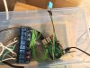
you're just about talking over my head a little. I think my sensor is on a "shield" already, I didn't buy the standalone sensor, I got the one on the little board, not sure it's technically shield.


I hope you mean by 6 channel that you are either monitoring and controlling six different parameters or even co2 sensors (that would be better so I could just trim down to a single channel easier). Right now all I have is the little arduino relay boards, may look into larger relays or contactors in time and all I need is binary, not pwn output yet, just on or off.

I don't have any plans that call for dimming or anything like a 358 yet, but that may change if I can really get this crap figured out. I've never been good at coding/programming even after college level classes.

going to check out your stuff now, thanks and I will try to spread the love a la the stinkmaster, as he commands it
 

completenoobie

Well-Known Member
yeah that last message was a bit over my head, I am just learning how to simply write high/low and delay. I certainly can't figure out on my own how to sample and the whole "while" thing. I get the concept but have zero idea how to implement. I have book after book on arduino and have watched a bazillion youtube vids and still can't retain the info
 

VegasWinner

Well-Known Member
yeah that last message was a bit over my head, I am just learning how to simply write high/low and delay. I certainly can't figure out on my own how to sample and the whole "while" thing. I get the concept but have zero idea how to implement. I have book after book on arduino and have watched a bazillion youtube vids and still can't retain the info
download the code in the link I provided, that will help a lot.
 

completenoobie

Well-Known Member
maybe the no dht file? I won't be needing temp/hum control or monitoring and looking at it, it does seem to only define 6 channels

edit: no that one has fades etc

I am not seeing exactly which file to look at? going through all of them, kinda.....
 

completenoobie

Well-Known Member
holy crap, that is way way far out and beyond my abilities to decipher, it does a million things and I would absolutely butcher it beyond being able making it able to run, I would start cutting stuff out and it would never work again. I wouldn't have the first clue how to edit that.

I copied it and pasted it into my my arduino editor just for shits and giggles and as is it would not verify, it just immediately said


Arduino: 1.6.13 (Windows 10), Board: "Arduino/Genuino Uno"

\AppData\Local\Temp\Temp1_working_greenhouse_controller.zip\working_greenhouse_controller\working_greenhouse_controller.ino:32:31: fatal error: LiquidCrystal_I2C.h: No such file or directory

#include <LiquidCrystal_I2C.h>

^

compilation terminated.

exit status 1
Error compiling for board Arduino/Genuino Uno.

This report would have more information with
"Show verbose output during compilation"
option enabled in File -> Preferences.
 

completenoobie

Well-Known Member
for example, this is the grand sum of my abilities with this tech and it took copying and pasting and a thousand headaches of editing and fixing before I could even get this to work


int relay = 13;

// the setup routine runs once when you press reset:
void setup() {
// initialize the digital pin as an output.
pinMode(relay, OUTPUT);
}

// the loop routine runs over and over again forever:
void loop() {
digitalWrite(relay, LOW); // turn the relay on (LOW is the voltage level)
delay(60000); // turns the pumps on for 1 minute
digitalWrite(relay, HIGH); // turn the relay off by making the voltage HIGH
delay(600000); // turn the pumps off for x/1000 seconds (10 minutes)
}
 

dstroy

Well-Known Member
holy crap, that is way way far out and beyond my abilities to decipher, it does a million things and I would absolutely butcher it beyond being able making it able to run, I would start cutting stuff out and it would never work again. I wouldn't have the first clue how to edit that.

I copied it and pasted it into my my arduino editor just for shits and giggles and as is it would not verify, it just immediately said


Arduino: 1.6.13 (Windows 10), Board: "Arduino/Genuino Uno"

\AppData\Local\Temp\Temp1_working_greenhouse_controller.zip\working_greenhouse_controller\working_greenhouse_controller.ino:32:31: fatal error: LiquidCrystal_I2C.h: No such file or directory

#include <LiquidCrystal_I2C.h>

^

compilation terminated.

exit status 1
Error compiling for board Arduino/Genuino Uno.

This report would have more information with
"Show verbose output during compilation"
option enabled in File -> Preferences.
You are missing a library "liquidcrystal_i2c".

"while" means do something if the while statement is true ie while(serial.available()) { do something }; it will never execute if the statement isn't true.

It's not hard, I really didn't know shit about programming and my control box works great. I wrote that code that you couldn't get to compile.

It won't compile on an uno, because it uses too many hardware serial ports. Even if you downloaded all of the libraries.

The cozir sensor is way different from an mg811, the mg811 only sends co2 data, and I'm not sure how it works because I haven't read the datasheet. If you read the datasheet it should give you some idea of how you can go about utilizing it for what you want.
 

dstroy

Well-Known Member
Another caveat about while() statements is that they block everything (except interrupts, which I don't know a lot about other than how to attach one to a pin) if their statement is true

ie
while(serial.available()){
do something forever until serial.available() == false
};
 
Top