VegasWinner
Well-Known Member
I use 22 gauge hobby wire easy and also solid for prototyping circuits on blank pcb is best for me.
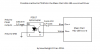
Are those resistance figures in the image not correct?optocoupler seems to be the preferred way- plus no inversion. Just a matter of finding whatever resistors you need


Because I have no experience with the octocoupler, and I'm quite familiar with NPN transistors and voltage regulators, and HLG drivers cannot dim to off on their own, they require a line-in relay.How does that schematic with the regulator look easier than the one with the optocoupler?
I think an optocoupler inverts the signal as well. Who cares though? Just invert it in the software. You can go from 0 to 255 for 0 to 100 or from 255 to 0.
The easiest thing is to use a dim-to-off driver. Then you won't need a relais.
So, in theory, all I need is an NPN and a 100k ohm resistor?I decided to go the transistor route cause I was getting confused by the optocoupler datasheet lol.
You shouldnt need the voltage regulator either, I dont think. The DIM controller is actually a constant current device (0.1mA), so the resistance actually sets the voltage. So if you have an on/off path- one of them should have 0 resistance (the off path), and the other path should still have a 100kOhm resistor (this converts the 0.1mA to the actual 10V required by the dimmer, 100,000ohm x 0.0001amp = 10V). This is why when the DIM leads arent connected (infinite resistance) it actually pumps out like 110% or something to the LEDs.
@xX_BHMC_Xx it also looks you're building something very similar to what im doing lol. We'll have to compare and contrast, and see who electrocutes themselves first.
Is that switching led integrated into the optocoupler? I'm assuming yes.@xX_BHMC_Xx, An optocoupler is basically a light sensitive transistor. So you don't switch this transistor by applying a current directly at the base, but through a led shining on the base.
But yeah, a transistor (or optocoupler) and resistor is all you need.
Yes.Is that switching led integrated into the optocoupler? I'm assuming yes.
So, will this work for a dim-to-off function, or will this pulse the whole fixture on/off with the PWM signal?Yes.
A problem with an optocoupler can be that the led can't switch fast enough. So a transistor is a safer bet anyway. There really is no need to use an optocoupler a tranistor works fine (better perhaps), but then neither is there a need to produce your own 10V source when the driver already supplies the source.
Yea the biggest mind-fuck for me was realizing that the DIM relied on a voltage of 0-10V, its kind of an odd way to look at it. But really it's a 0.1mA source that expects a resistance of 0-100.Yes.
A problem with an optocoupler can be that the led can't switch fast enough. So a transistor is a safer bet anyway. There really is no need to use an optocoupler a tranistor works fine (better perhaps), but then neither is there a need to produce your own 10V source when the driver already supplies the source.
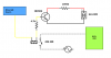
Put a 100kOhm resistor in parallel with the dimmer. This sets the default path of 100%=10V. Not sure specifically what the 10k is for.So, will this work for a dim-to-off function, or will this pulse the whole fixture on/off with the PWM signal?
Like this?Put a 100kOhm resistor in parallel with the dimmer. This sets the default path of 100%=10V. Not sure specifically what the 10k is for.
The relay looks good, might want to do a small pull-down resistor to keep bleed away on the relay coil. But fuck power efficiency lol Probably not a concern.
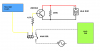
yep, LGTM. Are you putting the relay on the power OUT from the driver, or the AC power in? I'm probably going to do the relay on the power OUT from the driver, not sure if there's any big difference.Like this?
Meanwell recommends using the relay on the line in, and not to have the unit powered on without a load. I'll just have to use another GPIO to control the relay, StormX has more than I need anyway. Thanks for the advice!yep, LGTM. Are you putting the relay on the power OUT from the driver, or the AC power in? I'm probably going to do the relay on the power OUT from the driver, not sure if there's any big difference.
EDIT: ooh, wait, i just saw the relay is in line with the PWM... that might cause some issues when the PWM is cycling. The PWM signal should drop to ground, or close to. I think you'll need another GPIO pin to control that. The SS relay might work where it is tho, depending on its characteristics, and the PWM frequency.
Yeah, I've seen similar products to that, but unless you only want to control the entire fixture at once, you're gonna have to cut the plugs and wire them in anyway. Might as well save some $$/space and use the SSR's, imo. Wiring AC is no different than wiring DC, just make sure it's not plugged in when you start making connections or touching leads.I did find one of these awesome relays (now that I know I have to use the AC input, good call @xX_BHMC_Xx):
https://www.adafruit.com/products/268
Just an inline AC 'cable' with a relay in the middle. I trust myself wiring AC as far as I can throw... myself.