Cloudline AI-CLS6 (S6) PWM control with RPI

Kervork

Well-Known Member
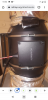
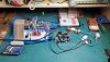
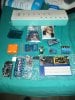
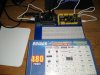
After seeing another users mods I bought one of these fans because I need exact control over air flow.
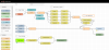
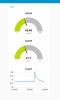
In this case I'm connecting a software pid controller to the fan to maintain temperature.
Hotter it gets, faster the fan goes.

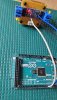
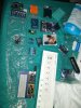
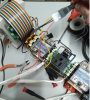
Much to my surprise the wiring was nothing like depicted previously. It seems that Cloudline made a few changes. Initially hooking up the RPI to ground and the PWM cable half worked. Speed went up and down but it wouldn't go much past about 30%.

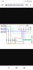
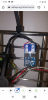
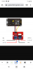
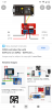
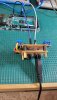
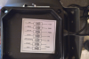
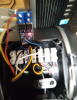
There is a diagram printed inside the cover. There are two bundles of wire. One for the AC power, one for the controller.

diag.png

cloudline_wiring.png

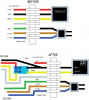
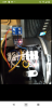
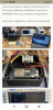
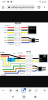
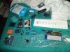
I used a molex connector to attach leads to the end of the control cable. Unfortunately in my screwing around I think I burned out the factory controller. No matter, it's of little use to me. There are 4 wires, I'm only using two of them, one is PWM GIPO18 and the other is ground. I'm using an EZ breakout board on the PI.

The PI is also going to be running lights, pumps, temp sensors as well as controlling the evap cooler during summer and a series of inline fans to control air flow.

pi.png

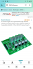
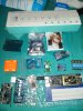
High Power 5-36V 400W MOS Field Effect Transistor Trigger Switch Driver Module PWM Regulator Electronic Switch Control Board DC Motor Speed Controller.

There are many sources, they are cheap.

isolator.png

The control voltage is reversed on the Cloudline. In the case of Nodered this means sending a 0 if you want full and 100 for off.

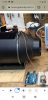
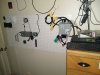
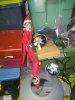
At some point my plan is to add a diverter to the exhaust so part of the time the fan is recirculating grow room air through the carbon filter and part of the time it is exhausing hot air. I could do this with two inline fans but it's a bit cheaper to use one fan. I may be setting up some sub-zero unheated grows where the only heat source is the light so in situations like that, air control is crucial.

I was going to do this with an ESP32 but for whatever reason neither of the two I had would flash properly. I though about using an ESP8266 but I'm concerned about the slow clock speeds. I've heard mixed things and don't know what to believe. In theory you might be able to fit an ESP with power supply in the box.
 

Attachments

Last edited:

Kervork

Well-Known Member
This is a simple temporary node red flow to control the fan. There are two main sections. The main section takes the temperature
every minute, converts it from C to F and sends it to a couple graph and indicator nodes on the dashboard. There is a series of forks
which map a temperature range to a PWM value. Note that 0 is full on and 100 is 0ff. After the PWM fan speed is calculate the message
gets sent to a blocking node. If the timer is on, the message is passed through, if the timer is off the message is blocked and replace
with 100 which is actually off. There is a simple manual override for testing. I will build this out later and have some delays, overrides etc.
At some point I expect to have more inline fans and may use one for filtering, one for exchange etc.

fan_control.png

Here is the dashboard using the standard nodered dashboard ui. You can see where I put the temp sensor in hot water to see if
the fan would go full on. It did.

dashboard.png

Approximate times involved...
Figuring out fan wiring, 4 hours. Don't ask why but now you have a diagram so it should take you 10 minutes.

Install Node Red on Raspberry Pi. 30 minutes actual time. I don't count wait time for updating install etc. I used the script which does the auto install so it's mostly copy paste and wait.

Build flow to control fan 45 minutes maybe.

Wire Raspberry Pi up with fancy outlets, din mount connectors, sensors etc. Lots of time but I now have a number of these mostly general purpose devices so I can grab one off the shelf and set it up for whatever task pretty rapidly. If you aren't using the Din mount connectors and rails you are missing out. My early builds used proto board and shit like that and any time a wire fell out it was hours wasted trying to figure out where to plug it back in. With the Din hardware you can screw the fuckers in tight and you can color code them.

Now I move on to the pumps and stop hauling water.

The evap cooler is run by a couple ESP8266's. I have a flow for it which automates it. Eventually the inline fan, room vent fan, evap cooler etc. will all work together in a coordinated fashion.

I would like to get the lights on PWM at some point because it would be cool to be able to dim them when I'm working on stuff. Getting blasted by white light at 10PM is not good for the sleep cycle.

I tried pasting the flow code here but it's over the size limit. With NR you can easily export and import other people's code so you can look at it, modify it etc. Big advantage over Arduino. No compiling, uploading or screwing around. Other than the node which converts from C to F there was no programming. There are probably nodes which could do that, I was just lazy and it's a whole one line of javascript.
 
This is a simple temporary node red flow to control the fan. There are two main sections. The main section takes the temperature
every minute, converts it from C to F and sends it to a couple graph and indicator nodes on the dashboard. There is a series of forks
which map a temperature range to a PWM value. Note that 0 is full on and 100 is 0ff. After the PWM fan speed is calculate the message
gets sent to a blocking node. If the timer is on, the message is passed through, if the timer is off the message is blocked and replace
with 100 which is actually off. There is a simple manual override for testing. I will build this out later and have some delays, overrides etc.
At some point I expect to have more inline fans and may use one for filtering, one for exchange etc.

View attachment 4834945

Here is the dashboard using the standard nodered dashboard ui. You can see where I put the temp sensor in hot water to see if
the fan would go full on. It did.

View attachment 4834949

Approximate times involved...
Figuring out fan wiring, 4 hours. Don't ask why but now you have a diagram so it should take you 10 minutes.

Install Node Red on Raspberry Pi. 30 minutes actual time. I don't count wait time for updating install etc. I used the script which does the auto install so it's mostly copy paste and wait.

Build flow to control fan 45 minutes maybe.

Wire Raspberry Pi up with fancy outlets, din mount connectors, sensors etc. Lots of time but I now have a number of these mostly general purpose devices so I can grab one off the shelf and set it up for whatever task pretty rapidly. If you aren't using the Din mount connectors and rails you are missing out. My early builds used proto board and shit like that and any time a wire fell out it was hours wasted trying to figure out where to plug it back in. With the Din hardware you can screw the fuckers in tight and you can color code them.

Now I move on to the pumps and stop hauling water.

The evap cooler is run by a couple ESP8266's. I have a flow for it which automates it. Eventually the inline fan, room vent fan, evap cooler etc. will all work together in a coordinated fashion.

I would like to get the lights on PWM at some point because it would be cool to be able to dim them when I'm working on stuff. Getting blasted by white light at 10PM is not good for the sleep cycle.

I tried pasting the flow code here but it's over the size limit. With NR you can easily export and import other people's code so you can look at it, modify it etc. Big advantage over Arduino. No compiling, uploading or screwing around. Other than the node which converts from C to F there was no programming. There are probably nodes which could do that, I was just lazy and it's a whole one line of javascript.
man, this is some real good work i can tell, and i will benefit from this, i see that you could benefit too from moving to home assistant, it has node red as an addon and makes creating entity and connecting to arduino and esp's and raspberry very easy i am in love with it since i started, i use node red too to control humidity, temperatures, lights and ph email alerts, but i am looking to implement more stuff like electricity consumption and much more. you should look into it the videos of ledg i linked in the other post are really good material to make yourself an idea of home assistant and how it works together with node red, its awesome, and i think you can import your flows to it with no effort at all. anyway good work mate.
 

Kervork

Well-Known Member
I have a grow log with more details. It's obvious I'm gonna need a lot more relays. Next step is to add an 8 port network relay. I will set up a VM with HA on it at some point and take a look. It would be a lot easier if someone would just pay me to do all this stuff so I could quit my day job. Day job is really interfering with my work and weed growing.
 
I have a grow log with more details. It's obvious I'm gonna need a lot more relays. Next step is to add an 8 port network relay. I will set up a VM with HA on it at some point and take a look. It would be a lot easier if someone would just pay me to do all this stuff so I could quit my day job. Day job is really interfering with my work and weed growing.
I can understand the time effort to automate something like a grow is huge, it took me almost 1,5 year to replicate the LEDG system.. i started from 0 and every time i added something (even stupid like a float valve to the diy humidifier to keep it topped up without refilling) i had more time to continue the project and i can tell you it is really worth your time.. all depends on what you are trying to do.. i am trying to cut myself out of the equation.. i was extremely lucky to find LEDG before i started, because all the system diagram, components, code etc was already there so i just had to slowly order(as the monthly budget allowed me since i am poor) like 150 usd of parts a month and start to put everything together.. i had to do only some slight modifications to the system since i use a RDWC and not coco like LEDG so no need to fertigate x amounts of time but just mix the solution inside the main tank, measure the whole system(main tank+plant buckets) to find out the weight of the water and let the automation do its thing..
I am now in the second week of tests with the system complete and even more in love with it.. very stable ec, ph, water and ambient temps, plants drink a LOT and even after a very aggressive and heavy defoliation and topping with the mainline technique they recovered in like 8 hours showing improvements on the selected shoots.. i am aiming to complete this cicle as test and then use the data of the entire grow to show the validity of the project to some big growers and MAYBE be hired to replicate it 1000 times bigger but it is not easy..
 

Elgove

Member
Wow this looks fantastic... Great job!!! And thank you for sharing... I just got my cloudline and I am looking to do something similar. If I may ask a question... Would you.mind sharing how to wire the MOSFET?

Thank you
 

Den0ts

New Member
Can you confirm the wiring on the mosfet? Im not usr eif i have the exact same ones, but from your picture it looks like red wire to +Out and yellow wire to -Out. But your diagram looks different, and people with pre-EC fans have it wired differently.
 

Den0ts

New Member
Also, IF you did still want to be able to use the stock controller, would you send the other yellow and red wire to the other side of the mosfet?
 
got a question how can I control more. I have multiple tents and AC Infinity cloudline 2 t6 and 5 t4 how can I control say even 4 of them this is what I have to work with I googled 4 or 5 different hookups yours,ledge,stud,and Cple other. I have all the MOSFETs 5 to 36v all the esp32s. Pwm to volt and volt to pwm,, 100k resistor,,,pc817,, adruino mega 256 plus with the extra pwmbI just ordered and booster to boost to 10v for the 2 t6 and also ordered a 4 channel easing edge l ac dimmer,,, 8 opto 22 relays breakout board kit,,sonoffth16 relay,,, dht22,,,bme280,,, ird520 MOSFETs,,,, 3 raps berry pi 4s,, 2 orange pi primes,,,2 atomic pis,,, and bunch different other adruinos,,, 7 inch touch screen for berry pi ,,,fire hd 10,,, and my desktop ,,, I'm running home assistant. Maybe nodered. I'm running. Lg 10kbtu Portable ac and voronado heater both prolly pull each 1200 and I am running 4 Bestva 2000 watt elite reflectors to 1600 watts.. and my grow light I'm working on with peltier pads that synergy they power the cooling fan. So heat from my light powers my peltier pads. Anyone can help me I'm mounting it in. Cple of those. Fancy stash logic boxes and one of my old pistols gin cases the cargo ones wanna mount everything in them and try to keep it mobile so I can close case up if I have to. Someone help plz
 

craggin

Active Member
I'm with @Den0ts & @Elgove as to asking about the exact wiring of the mosfet. The diagram and the photo don't actually jive. In the parent thread, @Jesusgrowsmygrass shows his to be hooked up with only the PWM (yellow wire) connected to -VIN & -VOUT. Granted he has what appears to be the older Cloudline, but seems like the power (+10V) and PWM would wire up the same regardless. I have a grow 3 weeks into flowering, otherwise I would try to get mine working and share a post of the wiring.
 
Any of these help I'm doing.it threw home assistant with an esp32 or other esp can control 2 with 1 and keep ac Infinity controller 67 also.
 

Attachments

Here check out this it's worth signing in up.


Attachments

craggin

Active Member
I pulled one of my CL6s out and did some tests to confirm wiring. The image showing the mosfet with red to VOUT+ and yellow to VIN+ is correct and works as desired. The schematic, as shown earlier, does not work. But, without this as a starting point, I would still be lost... Thanks OP!
 
I am just curious could any of this and all of these s*** be done excuse my language instead of my spec controllers with a simple pwm to voltage module or voltage to pwm whether you're running milliamp current DC current or whatever current you're running instead of my spec couldn't you do pwm like the ones I showed below. Cuz my idea is either stealing the signal and just tapping into the signal or completely bypassing the AC Infinity control altogether but I would rather like to keep the controller how would I go about that just running the mosfets and the l298
 

craggin

Active Member
@wieczorekfloorz, not sure I follow... I've designed my own automated control system for everything in a grow room or tent, such as lights, light fixture vent fans, exhaust fan, circulation fans, co2, hydroponic pumps, etc. However, after upgrading to the AC Infinity Cloudline fans, I was forced to use their controller(s). I even bought one the fancier models that can control 2 fans, but it isn't as "smart" as the manufacturer claims. For instance, I needed to run one at one speed and the other at a different speed - and their "smart" controller is incapable. You also cannot mix the timer function with the temp or humidity control. So, I wanted to integrate the Cloudline fans into my own system for better automation (someone else on this forum said as much too - so I'm not the only one interested in this idea). Researching how to reverse engineer the Cloudline lead me to this forum/post.

So, yeah - there's probably a million ways to skin this snake and use simple pwm to voltage modules as you say - but that may or may not meet one's objective. Here's a few photos of the circuit board I crafted to support 2 CL6s, each with its own on/off/speed settings based upon various sensor readings. This board plugs into an Arduino Mega for output control, while an Arduino Uno collects all the sensor data. Earlier versions of my system used a single Arduino Mega, but the code became too bloated and unwieldy. An RPi acts as the main brains for the automation and supports all the other things like Wifi access, touchscreen, and a web console. I've also included a pic of my latest prototype in-progress.
20211201_144646.jpg 20211226_161446.jpg 20211226_161617.jpg
 

craggin

Active Member
got a question how can I control more. ...
I would consider a design that uses one controller per grow room/tent. Then each controller would be managed by a single interface, maybe running in the cloud. This is what my design essentially does - one controller per room/tent, and each available through a single app. This was modeled from the SmartThings & Home Assistant approaches towards multiple "locations" (i.e. automate my main house one way, my vacation home another). My main controller unit has ( 8 ) 110VAC outlets & ( 4 ) 12VDC jacks, but can only handle 15A total current (needed to keep it at 15A max to run in most US homes, unless connected to a 20A breaker). I extended the current limitations by implementing a Wifi module (running on a RPi Zero W) that I coded to support the TP-Link protocol. I can now use unlimited number of TP-Link Smart Plugs that expand my device capability beyond the 8x4/15A limitation. I'm currently only planning on supporting ( 2 ) AC Infinity CL, but with the Mega I have more than enough PWM outputs to support more. I have been contemplating a tent design that would use ( 3 ) CLs, so maybe I need to incorporate that now. Problem then becomes physical space within the plastic project enclosure!
 
Damn nice last night I about had nervous breakdown trying to setup home assistant on confused so I guess I'm stuck with a home assistant container. I wanted it installed on a is like Raspbian or raspberry pi is. But it's so confusing Linux,ssd,ssh, scripts on adruino. My original plan was a hybrid system like ledg ledgardener ,, and. Kyle Gabriel my codo app open source grow room controller. I spent over a grand on everything. Researched here's some of the stuff I got. And CPL links to what I'm trying to do. Maybe someone can help me. Trying to make hybrid system from 2 other systems. 1 https://ledgardener.com/forum/viewtopic.php?t=5698


And

2.https://kylegabriel.com/projects/2020/06/automated-hydroponic-system-build.html

Here is a link for you craggin you like this smart plugs and AC dimmers.

Here is some of the stuff I got to build my setup.
 

Attachments

Top