Gotcha. I'm not too familiar with proto-board. A wire splitter would work the same right? At least until I educate myself on that and mosfets. Makes things more clear for me though so ty for that.Yes... That is how I am doing it. I have the protoboard acting as the splitter, and each buck has its own feed from the board (post-MOSFETs), but only one 12V rail supplies the board.
diy pc grow slightly different. (concept)
- Thread starter panast
- Start date
heckler73
Well-Known Member
The MOSFETs aren't necessary. I'm just using them as switches. For wiring to the ATX, you just need to hook them in AFAIK.Gotcha. I'm not too familiar with proto-board. A wire splitter would work the same right? At least until I educate myself on that and mosfets. Makes things more clear for me though so ty for that.
As for that adjustable buck, I believe that will work, but you need two chips in parallel on it, probably, based on the current output (2A const current)
This good for driving just one then?http://m.ebay.com/itm/1-pcs-10W-12V-24V-DC-LED-Constant-Current-Driver-Power-900mA-High-Power-LED-/252038852796?nav=SEARCHAs for that adjustable buck, I believe that will work, but you need two chips in parallel on it, probably, based on the current output (2A const current)
heckler73
Well-Known Member
Yes, that is exactly what I am using for mine. They can also be modified, if need be.This good for driving just one then?http://m.ebay.com/itm/1-pcs-10W-12V-24V-DC-LED-Constant-Current-Driver-Power-900mA-High-Power-LED-/252038852796?nav=SEARCH
Nice getting er all straightened out piece by piece with your help. So ty again.Yes, that is exactly what I am using for mine. They can also be modified, if need be.
I'd have to spend a little money but I was wondering if something like this could be incorporated, maybe between psu and splitter? In my case maybe 2 channels drive the top and 1 channel drive the bottom? Idk if it would work for sure but it would be cool I think.
https://www.amazon.com/gp/aw/d/B00OH9ENVW/ref=ox_sc_act_image_3?ie=UTF8&psc=1&smid=A1HPBDJJIXKXS7
heckler73
Well-Known Member
Yes, that looks like it could work. You could bridge the ATX outputs and plug them all into the input, since each channel can handle 4A. Although, I seem to recall one needs to do a mod to the ATX in that case.I'd have to spend a little money but I was wondering if something like this could be incorporated, maybe between psu and splitter? In my case maybe 2 channels drive the top and 1 channel drive the bottom? Idk if it would work for sure but it would be cool I think.
Not too familiar with modding or bridging the rails, have been reading into it. Would that work off 1 12v rail?Yes, that looks like it could work. You could bridge the ATX outputs and plug them all into the input, since each channel can handle 4A. Although, I seem to recall one needs to do a mod to the ATX in that case.
heckler73
Well-Known Member
Oh sure...I was just thinking if you really wanted to load that digital switch, it will take 4A per channel.Not too familiar with modding or bridging the rails, have been reading into it. Would that work off 1 12v rail?
Ok, well I think i kinda got it all sorted out in my head at least. I got some sets of 3w uv leds on the way, and driver/light combos in my cart.Oh sure...I was just thinking if you really wanted to load that digital switch, it will take 4A per channel.
Just wondering, what are the measurements on your heatsink? Is it calculated out or just overkill?
heckler73
Well-Known Member
11.25 x 7.5 in., 1/8 in. checkerplate aluminum.Just wondering, what are the measurements on your heatsink? Is it calculated out or just overkill?
It is ~48 degC in the center of the plate (a little warm) without a VGA cooler.
Overkill?
Was wondering because I was hoping if I put an aluminium sheet at the halfway point of the box it could serve as the floor for the top chamber and the heatsink for the bottom chamber without losing too much height. Not quite sure how to cool the heatsink/floor without sacrificing too much height.11.25 x 7.5 in., 1/8 in. checkerplate aluminum.
It is ~48 degC in the center of the plate (a little warm) without a VGA cooler.
Overkill?not even adequate. I would recommend something a little heavier, like 1/4 in. plate, at least, unless you intend to use proper heatsinking.
heckler73
Well-Known Member
What are you making this cabinet from? Dimensions, etc.Was wondering because I was hoping if I put an aluminium sheet at the halfway point of the box it could serve as the floor for the top chamber
Stack on gun cabinet. 55" tall 9" deep 21" wide looks like 1/8" stainless steel painted black. Similar to this.What are you making this cabinet from? Dimensions, etc.
Attachments
-
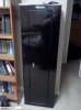 6.7 KB Views: 10
 -
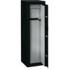 3.2 KB Views: 10
1 for bonsai moms and 1 for flower chamber. The heating mat idea is what I had in mind with that.You have enough room with that to sacrifice an inch or two for heatsinking. Conceivably, one could use that thermal energy from the LEDs as a 'heating mat'. What are you planning to have on top?
heckler73
Well-Known Member
I don't know if it's very wise to work with PCB-based electronics if you're not familiar with prototype boards. Furthermore, I'm not using the board for "drivers", I'm using it for "switches"; they aren't necessary for what you want to do, I think, unless you're wanting to run both chambers from one supply.How big of a protoboard do you need for the 4 drivers? Would breadboard work even though its meant for temp projects, or is protoboard better? Do you use project boxes for the protoboard?
Are you familiar with Ohm's Law? For example, if you have 10W and 900mA of current, what is the equivalent resistance (to four decimal places)?
Doesn't seem that difficult after researching it a little.I don't know if it's very wise to work with PCB-based electronics if you're not familiar with prototype boards.
Not sure if I can make 2 12v rails off a generic atx psu. But I'm sure my other one already has 2 12v rails on it.unless you're wanting to run both chambers from one supply.
I've read ohms law before, but never really had to use it outside of car stereo/amplifier installation. Wiring down 4 ohms to 2 or 2 ohms to 1.Are you familiar with Ohm's Law? For example, if you have 10W and 900mA of current, what is the equivalent resistance (to four decimal places)?
I can find calculators that will fill in the blanks for me. I.e. 12.34568