Experienced Electrician! Here to Answer Any and All Growroom Electrical Questions

Renfro

Well-Known Member
I just split the 240 by running the 2 main wires to each 120 breaker, instead of both of them going into a bigger 240 breaker.
Why? You have a pic? Really man, pics would be worth a lot more than words when it comes up to the wiring. If it's a tandem breaker you are pulling the singles from then they are both on the same phase for example. I really need to see how you wired each panel, cover off.

If you have any 240 volt loads you really want both legs to trip if there is an overcurrent condition.
I had got a fat weatherproof 240v 30ft 50 amp RV extension cord that I cut the end off of and wired into a 70 amp dual breaker slot sub panel from lowes.
The question is, is each wire in the cord basically rated for max of 25 amps?
What gauge is the cord? If it's a 50 amp cord it should be at least #6 copper and it's designed to run on a 50 amp breaker that generally trips around 80% continuous so about 40 amps available at 240 volts or 2x40 amps @ 120 volts.

You have me rather confused as to exactly how this is wired so if you post pics of how it's all wired up I can perhaps help locate the problem/s.
 

ypbiscuit

Member
Hi Renfro. By chance did you see my post on trying to connect a subpanel from my garage to a cargo container I just bought ?

I'm outside playing with my new puppy , looking at the wiring now .


Why? You have a pic? Really man, pics would be worth a lot more than words when it comes up to the wiring. If it's a tandem breaker you are pulling the singles from then they are both on the same phase for example. I really need to see how you wired each panel, cover off.

If you have any 240 volt loads you really want both legs to trip if there is an overcurrent condition.


What gauge is the cord? If it's a 50 amp cord it should be at least #6 copper and it's designed to run on a 50 amp breaker that generally trips around 80% continuous so about 40 amps available at 240 volts or 2x40 amps @ 120 volts.

You have me rather confused as to exactly how this is wired so if you post pics of how it's all wired up I can perhaps help locate the problem/s.
 

Sleez

Well-Known Member
Did anybody confirm if we could use meanwell drivers on 240v? Do I need an adapter? On my light controller is has universal sockets I guess u would call it. To where I can just plug in regular plug instead on the 220 or 240v plug
 

Wastei

Well-Known Member
This doesn't really apply to AC current for your project. In theory you would be wiring this in series, just wire the black to the black, white to the white, and if there is a green or just naked wire: green/naked to green/naked. And that is it.
What are you talking about? Of course you must wire this in parallel connection. Otherwise you will not get uniform voltage. Why the hell would you leave earthing out of the wiring?

Sure you're the right person to give out electrical advices?
 

GlueSniffer

Active Member
What are you talking about? Of course you must wire this in parallel connection. Otherwise you will not get uniform voltage. Why the hell would you leave earthing out of the wiring?

Sure you're the right person to give out electrical advices?
lol I saw this thread, read the first answer - and thought the same as you. White to white, black to black is correct - but it is not SERIES. If you want the same voltage at each, you use parallel. That guys been confused for a decade.
 

Drop That Sound

Well-Known Member
Why? You have a pic? Really man, pics would be worth a lot more than words when it comes up to the wiring. If it's a tandem breaker you are pulling the singles from then they are both on the same phase for example. I really need to see how you wired each panel, cover off.

If you have any 240 volt loads you really want both legs to trip if there is an overcurrent condition.


What gauge is the cord? If it's a 50 amp cord it should be at least #6 copper and it's designed to run on a 50 amp breaker that generally trips around 80% continuous so about 40 amps available at 240 volts or 2x40 amps @ 120 volts.

You have me rather confused as to exactly how this is wired so if you post pics of how it's all wired up I can perhaps help locate the problem/s.

Thanks, phase was definately one of the words I was looking for., and something i think might be off.

This is the cord: http://www.camco.net/power-grip-50-amp-pigtail-power-cord-hardwire-30-foot-55189
4d60343f-c3e1-4b60-a944-e76315967e9b_1.8269d5fcfa1f3ea34871301bebf12c1b.jpeg

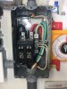
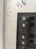
I have a 50 amp breaker in the main panel outside on a post. From there I pulled 4 correctly gauged solid wires through some flex conduit into a 4 prong 50 amp receptical, on the same post below.. sometimes I plug the welders in too, just wired as normal.

From there I plugged in the male end of the rv cord ,and ran it over to the trailer. The other end I pulled throught conduit and cut off the female end , and then wired into the sub panel inside. I did not use the bond screw.
047569804366.jpg

I put 2 tandem breakers in, same brand as the box, a double 20 and a double 15 for a total of 70 amps and 4 circuits. I suppose its made to do either dual 120s or a single 240 breaker for a hot tub, etc. The tandem 20.. each one go's a few feet into their own single dedicated 20 amp recepticals with heavier duty wire into the flower room. On the tandem 15, one is all the main workroom recepticals, and the other just for the veg room, etc. It does have a gfci toward the end of the circuit for a pump on one of the 15s.. should it actually be the closest outlet first to protect all the boxes instead, or im not even suppost to have one at all the way i'm wired up? Could that be my problem?
IMG_1878.JPG
The weird part is i have the problem tripping breakers most on the 20s. My 1000 watt digitals fire no problem, but running a skill saw will trip it. Not as bad on one of the 15 amp circuits for some reason, but still does on those too, even plugged directly in without an extension. Air compressors, space heaters, any thing with a higher starting amperage will kit it.

Im not sure what gives when I have some serious amperage running up in there (just to run a small hobby garden), and want to run power tools outside once in awhile too when not running lights.

Ill be back with pics soon.
 
Last edited:

Drop That Sound

Well-Known Member
Why? You have a pic? Really man, pics would be worth a lot more than words when it comes up to the wiring. If it's a tandem breaker you are pulling the singles from then they are both on the same phase for example. I really need to see how you wired each panel, cover off.

If you have any 240 volt loads you really want both legs to trip if there is an overcurrent condition.


What gauge is the cord? If it's a 50 amp cord it should be at least #6 copper and it's designed to run on a 50 amp breaker that generally trips around 80% continuous so about 40 amps available at 240 volts or 2x40 amps @ 120 volts.

You have me rather confused as to exactly how this is wired so if you post pics of how it's all wired up I can perhaps help locate the problem/s.
Thanks again.
 

Attachments

Renfro

Well-Known Member
Also, in the first image, is that top neutral wire on the bus showing signs of heat (dark insulation near the terminal). Make sure that it's tight, loose terminals can cause that to happen.
 

Renfro

Well-Known Member
BTW very neat wiring job but you might wanna ditch the zip ties in the panel. I despise that, bundled wires in a panel. If one wire gets too hot and melts you have a much bigger mess when they are all tied in a bundle.
 

Drop That Sound

Well-Known Member
Ok im headed back to the main panel, it had been raining and wet and I found another problem so didnt wanna open it yet without tools & a new receptical. I found out that one of the 20s (I beleive is attached to that main 50 im using in the middle) is going to another outdoor receptical with a gfci that quit working. It worked when I put in the sub panel a few years back.. find out soon when I can see and take pics.

So its actually 90 amp shared breaker im working from. The third 20 amp circuit on the main breaker im not too sure, runs out to the old shed I think.

Ill remove the zips and check for heat stress too On the nuetral. Be back again soon, appreciate your inspection!
 

Renfro

Well-Known Member
Ok im headed back to the main panel, it had been raining and wet and I found another problem so didnt wanna open it yet without tools & a new receptical. I found out that one of the 20s (I beleive is attached to that main 50 im using in the middle) is going to another outdoor receptical with a gfci that quit working. It worked when I put in the sub panel a few years back.. find out soon when I can see and take pics.

So its actually 90 amp shared breaker im working from. The third 20 amp circuit on the main breaker im not too sure, runs out to the old shed I think.

Ill remove the zips and check for heat stress too On the nuetral. Be back again soon, appreciate your inspection!
If you have an amp clamp handy you might put it on the hot wire coming off the breaker thats tripping when you start the saw. See whats going on from that angle when the saw is fired up. If there are other loads on there then it will be apparent as well.
It does have a gfci toward the end of the circuit for a pump on one of the 15s.. should it actually be the closest outlet first to protect all the boxes instead, or im not even suppost to have one at all the way i'm wired up? Could that be my problem?
On the GFI question it all depends on if you want the other receptacles chained off the protected side of the GFI. Then they are all protected and if the GFI trips all those receptacles would shut down. Might not want something like a fan shut down because a pump has a problem so it's up to you what receptacles you want protected by the GFI. If the GFI is the problem then I would suspect that it would trip, thats usually their problem, haven't heard of one drawing current on it's own without melting down lol. Again the amp clamp will help find if there is any current being drawn, if you suspect the GFI is somehow pulling current then just press it's test button and trip it. Then see if the draw is gone. I don't think that it's the problem though.
 

Troutguide

Active Member
So I want to set up an 18 light room 1000w hps. How do I set up a timer for all of the lights? Looking for the easiest, cheapest solution that is not manual.
 

Renfro

Well-Known Member
So I want to set up an 18 light room 1000w hps. How do I set up a timer for all of the lights? Looking for the easiest, cheapest solution that is not manual.
What lights? Some lights can simply be plugged in and remotely controlled by specific means. If you are just talking generic lights that have no remote control feature then a lighting controller is the way to go.


You can use one big controller or a couple smaller ones. I prefer the smaller ones without a timer and plug the trigger cord into a reliable digital timer.
 

1212ham

Well-Known Member
Did anybody confirm if we could use meanwell drivers on 240v? Do I need an adapter? On my light controller is has universal sockets I guess u would call it. To where I can just plug in regular plug instead on the 220 or 240v plug
Look up the datasheet for your driver. Meanwell drivers operate on 90 - 305 volts. As for an adapter, I don't know what plug is on your driver. If it fits your controller it should be ok.
 

Sleez

Well-Known Member
Look up the datasheet for your driver. Meanwell drivers operate on 90 - 305 volts. As for an adapter, I don't know what plug is on your driver. If it fits your controller it should be ok.
Thanks man. Appreciate the help. I ended up calling meanwell directly. And he told me I could with no adapters. Like you said it operates up to 305 volts.
 
Hi there fellow RIU'ers... Over and over again I continualy see new threads and posts about electrical work question and thought I would post a couple threads to help you guys the same way all of you who have done such a great job having helped me... So, Do you have a grow room question about how to wire something up, or what are the safest ways of doing things? The most important one I see alot is people running lights and fans off power chords... I have wired my own grow room and will post an example of my work.

Please, if you have any questions and are unsure of what to do or if what you are doing is safe, PLEASE! ask me first if you are even a tad bit unsure. I would hate to hear anyone have an electrical fire because they didn't quite know what they were doing when all they needed to do was to ask a couple of questions... I will do my best to point you in the right direction.

If you want to do some wiring your self, I will either let you know if your project is too complicated if your not handy with electrical, or, IF YOU ASK, I will walk you thru your project step by step.

So please, ASK AWAY!!!

You can post questions here but you may not get your question answerd on the thread, best way to go about it is PM me. You will forsure get a response back.

PS Even if you have basic around the home electrical questions, shoot em my way.
Hi. How do I know how much amp run in my breaker box. I don’t know if I asked that correctly. Gracias.
 

guitarguy10

Well-Known Member
I am waiting on some HLG QB120 boards (70W each) and a user here @ilovereggae is helping me out with some drivers, wagos, etc. etc. (very much appreciated btw). I will be wiring 2 boards in parralel on one driver (Delta LNE-24V120WDAA) with a potentiometer.

The only thing I have left is the wire to use on the DC side. I have tonnes of 22 gauge wire that I use with my arduino and rasp. pi microcontrollers. Would this wire be sufficient/safe enough to carry the load this setup will produce?

The only source of information I could find on the National Electric Code on maximum rated amperage for a given wire gauge only goes as 'low' as 14 gauge wire, it doesn't show the max amperage for anything above (thinner) then 14 gauge:
 

2com

Well-Known Member
I am waiting on some HLG QB120 boards (70W each) and a user here @ilovereggae is helping me out with some drivers, wagos, etc. etc. (very much appreciated btw). I will be wiring 2 boards in parralel on one driver (Delta LNE-24V120WDAA) with a potentiometer.

The only thing I have left is the wire to use on the DC side. I have tonnes of 22 gauge wire that I use with my arduino and rasp. pi microcontrollers. Would this wire be sufficient/safe enough to carry the load this setup will produce?

The only source of information I could find on the National Electric Code on maximum rated amperage for a given wire gauge only goes as 'low' as 14 gauge wire, it doesn't show the max amperage for anything above (thinner) then 14 gauge:
For the DC side? I'd suggest you get some 18awg solid. "Shaxon" or "NTE" or whatever brand from amazon is good. Or maybe some 18awg solid "door bell" wire from home store, etc.
 
Top