What? You want to dim 36 drivers to "max off"? Why use an opto isolator?
The Meanwell 3 in 1 dimming function can be controlled with 1~10VDC, PWM or resistance. PWM with a resistor is impossible, using resistance has nothing to due with controlling PWM, or pulse width modulation.
The Meanwell 3 in 1 dimming function can be controlled with 1~10VDC, PWM or resistance. PWM with a resistor is impossible, using resistance has nothing to due with controlling PWM, or pulse width modulation.
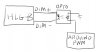
The opto isolator serves as a switch with the emitter and collector on the Dim- and Dim+. The PWM goes to the anode of the opto to open and close the Dim. The resistor is to prevent “full off” of the Dim. I’ve read numerous places that the number of drivers divided into 10K is the value to put in series when dimming multiple drivers in parallel. I just want to know if there’s an upper limit to the number of drivers or if I need to have a separate opto every X drivers.
Hmm... I don't think you can use both resistance and PWM dimming. For resistance dimming, a 10k resistor is often used in series with a pot, mostly to due to many pots being a little under their rated value, and 100K or higher is needed to achieve full power.
I'll admit some confusion, never heard of using both resistance and pwm. A resistor in series with the driver and opto? Why prevent full off? Why not do it with PWM? Also, Meanwell datasheets say 10v pwm, not switched pwm. We'll figure it out, lots of smart people here.
I'll admit some confusion, never heard of using both resistance and pwm. A resistor in series with the driver and opto? Why prevent full off? Why not do it with PWM? Also, Meanwell datasheets say 10v pwm, not switched pwm. We'll figure it out, lots of smart people here.
Last edited:
This is the idea. My question is, can I put the dim+ and dim- from multiple drivers all across one opto and if so, how many? Or do I need a separate opto for each driver?
I’m assuming that with the 10v PWM, the 10v is already present because when open, you get full LED, and when shorted, it goes full off. So the opto would be toggling the connection according to the PWM.
As for the resistor, this is essentially slamming the dim leads all the way to zero with pwm, and because it was recommended with potentiometer dimming that there be a resistor to prevent going to zero, I assumed it would be necessary.
Last edited: