MidnightSun72
Well-Known Member
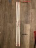
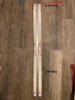
So For my 600W build I am use the H series H652D 22.5Vf with a 48V LG driver.
I am planning to wire either as following. One way I am certain minimizes the chance of voltage
hogging. The other way I am not so sure if it's risky. So would like more experiences LeD builders to weigh in
Option 1. I'll cut the wires at the same length and connect into a wago This will give me equal runs and thus maintain even Vf among all strings as best as possible
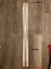
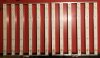
Option 2: if I can get away with this I'd prefer it. Because parsley one set of strips off the other set. But I know this might give lower voltage to the secondary LED strings. Do you think I will increase my chance of voltage hogging? Or is it pretty much nothing to worry about?

Thoughts?
edit I fucked up option 2 Brb fixing. Lol
I am planning to wire either as following. One way I am certain minimizes the chance of voltage
hogging. The other way I am not so sure if it's risky. So would like more experiences LeD builders to weigh in
Option 1. I'll cut the wires at the same length and connect into a wago This will give me equal runs and thus maintain even Vf among all strings as best as possible
Option 2: if I can get away with this I'd prefer it. Because parsley one set of strips off the other set. But I know this might give lower voltage to the secondary LED strings. Do you think I will increase my chance of voltage hogging? Or is it pretty much nothing to worry about?
Thoughts?
edit I fucked up option 2 Brb fixing. Lol
Last edited: