ectrical ballast (sometimes called
control gear) is a device intended to limit the amount of
current in an
electric circuit. Ballasts vary greatly in complexity. They can be as simple as a series
resistor as commonly used with small
neon lamps or
light-emitting diodes (LEDs). For higher-power installations, too much energy would be wasted in a resistive ballast, so alternatives are used that depend upon the
reactance of
inductors,
capacitors, or both. Electronically-controlled ballasts may incorporate a microprocessor to form a so-called "digital ballast".
Contents
[hide]
[edit] Current limiting
Ballasts are used where an
electrical load cannot effectively regulate its current use. These are most often used when an electrical
circuit or device presents a
negative (differential) resistance to the supply. If such a device were connected to a constant-
voltage power supply, it would draw an increasing amount of current until it was destroyed or caused the power supply to fail. To prevent this, a ballast provides a positive
resistance or
reactance that limits the ultimate current to an appropriate level. The combination of a negative-resistance characteristic and a series impedance allows a stable operating point to be maintained. Examples of such negative-resistance devices are
gas-discharge lamps.
[edit] Resistors
The term
ballast resistor primarily refers to a
resistor which compensates for normal or incidental changes in the physical state of a system. It may be a fixed or variable resistor.
[edit] Fixed resistors
For simple, low-powered loads such as a neon lamp or LED, a fixed resistor is commonly used. Because the resistance of the ballast resistor is large it dominates the current in the circuit, even in the face of
negative resistance introduced by the neon lamp.
The term also refers to an
automobile engine component that lowers the supply
voltage to the
ignition system after the engine has been started. Because cranking the engine causes a very heavy load on the
battery, the system voltage can drop quite low during cranking. To allow the engine to start, the ignition system must be designed to operate on this lower voltage. But once cranking is completed, the normal operating voltage is regained; this voltage would overload the ignition system. To avoid this problem, a ballast resistor is inserted in series with the supply voltage feeding the ignition system. Occasionally, this ballast resistor will fail; the classic symptom of this failure is that the engine runs while being cranked (while the resistor is bypassed) but stalls immediately when cranking ceases (and the resistor is re-connected in the circuit).
Modern electronic ignition systems do not require a ballast resistor as they are flexible enough to operate on the low cranking voltage or the ordinary operating voltage.
In some old
AC/DC receivers (universal sets), the
vacuum tube heaters are connected in series. Since the voltage drop across all the filaments in series is sometimes less than the full mains voltage, it was often necessary to get rid of the excess voltage. A ballast resistor was often used for this purpose, as it was cheap and worked with both AC and DC.
[edit] Self-variable resistors
Some ballast resistors have the property of increasing in
resistance as current through them increases, and decreasing in resistance as current decreases. Physically, some such devices are often built quite like
incandescent lamps. Like the
tungsten filament of an ordinary incandescent lamp, if
current increases, the ballast resistor gets hotter, its resistance goes up, and its voltage drop increases. If
current decreases, the ballast resistor gets colder, its resistance drops, and the
voltage drop decreases. Therefore the ballast resistor reduces variations in current, despite variations in applied voltage or changes in the rest of an electric circuit. These devices are sometimes termed
barretters.
This property can lead to more precise current control than merely choosing an appropriate fixed resistor. The power lost in the resistive ballast is also reduced because a smaller portion of the overall power is dropped in the ballast compared to what might be required with a fixed resistor.
In times past, household
clothes dryers sometimes incorporated a
germicidal lamp in series with an ordinary incandescent lamp; the incandescent lamp operated as the ballast for the germicidal lamp. A commonly used light in the home in the 1960s in 220-240V countries was a circleline tube ballasted by an under-run regular mains filament lamp. Self ballasted
mercury-vapor lamps incorporate ordinary tungsten filaments within the overall envelope of the lamp to act as the ballast, and it supplements the otherwise lacking red area of the light spectrum produced.
[edit] Ballast factor
For a lighting ballast, the
ballast factor is defined as the light output (in
lumens) with a test ballast, compared to the light output with a laboratory reference ballast that operates the lamp at its specified nominal power rating.
[1] [2] The ballast factor of practical ballasts must be considered in
lighting design; a low ballast factor may save energy, but will produce less light. With fluorescent lamps, an electronic ballast may produce more light than the reference test ballast, which operates the lamp with
line frequency current; such electronic ballasts have a ballast factor greater than one.
[edit] Reactive ballasts
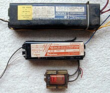

Several typical magnetic ballasts for
fluorescent lamps. The top is a high-power factor, lead-lag ballast for two 30–40 W lamps. The middle is a low power factor ballast for a single 30-40 W lamp while the bottom ballast is a simple inductor used with a 15 W preheat lamp.
Because of the power that would be lost, resistors are not used as ballasts for lamps of more than about two watts. Instead, a
reactance is used. Even so, losses in the ballast due to its resistance and losses in its magnetic core may be significant, on the order of 5 to 25% of the lamp input wattage. Practical lighting design calculations must allow for ballast loss in estimating the running cost of a lighting installation.
An
inductor is very common in line-frequency ballasts to provide the proper starting and operating electrical condition to power a
fluorescent lamp,
neon lamp, or
high intensity discharge (HID) lamp. (Because of the use of the inductor, such ballasts are usually called
magnetic ballasts.) The inductor has two benefits:
- Its reactance limits the power available to the lamp with only minimal power losses in the inductor
- The voltage spike produced when current through the inductor is rapidly interrupted is used in some circuits to first strike the arc in the lamp.
A disadvantage of the inductor is that current is shifted out of phase with the voltage, producing a poor
power factor. In more expensive ballasts, a
capacitor is often paired with the inductor to correct the power factor. In ballasts that control two or more lamps, line-frequency ballasts commonly use different phase relationships between the multiple lamps. This not only mitigates the flicker of the individual lamps, it also helps maintain a high power factor. These ballasts are often called
lead-lag ballasts because the current in one lamp leads the mains phase and the current in the other lamp lags the mains phase.
For large lamps, line voltage will not be sufficient to start the lamp, so an
autotransformer winding is included in the ballast to step up the voltage. The autotransformer is designed with enough
leakage inductance so that the current is appropriately limited.
Because of the large inductors and capacitors that must be used, reactive ballasts operated at line frequency tend to be large and heavy. They commonly also produce acoustic
noise (line-frequency
hum).
Prior to 1980 in the United States,
PCB-based oils were used as an insulating oil in many ballasts to provide cooling and electrical isolation (see
transformer oil).
[3][4] When removed from service, such ballasts must be handled as
hazardous waste.
[edit] Electronic ballasts
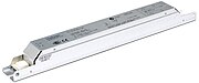
A2 Class Electronic ballast for 2 pcs of 58W fluorescent lamps

Electronic ballast of a
compact fluorescent lamp
Electronic ballasts usually change the frequency of the power from the standard mains (e.g., 60 Hz in U.S.) frequency to 20,000 Hz or higher, substantially eliminating the
stroboscopic effect of flicker (a product of the line frequency) associated with fluorescent lighting (see
photosensitive epilepsy). In addition, because more gas remains ionized in the arc stream, the lamps actually operate at about 9% higher efficiency above approximately 10 kHz. Lamp efficiency increases sharply at about 10 kHz and continues to improve until approximately 20 kHz.
[5] Because of the higher efficiency of the ballast itself and the improvement of lamp efficiency by operating at a higher frequency, electronic ballasts offer higher system efficiency. In addition, the higher operating frequency means that it is often practical to use a capacitor as the current-limiting reactance rather than the inductor required at line frequencies. Capacitors tend to be much lower in loss than inductors, allowing them to more closely approach an "ideal reactance".
Electronic ballasts are often based on the
SMPS topology, first rectifying the input power and then chopping it at a high frequency. Advanced electronic ballasts may allow dimming via
pulse-width modulation and remote control and monitoring via networks such as
LonWorks,
DALI,
DMX-512,
DSI or simple analog control using a
0–10 V DC brightness control signal.
[edit] Digital HID (DHID) ballasts
A
digital HID (DHID) lamp ballast is an electronic ballast that uses a
microprocessor to control and regulate a
High-Intensity Discharge (HID) lamp. The
firmware can provide control algorithms to supply varying lamp currents during start-up and during lamp operation. The
firmware controls the initial voltage strike to the bulb to start it and then controls current in the bulb for the most efficient burning of the lamp.[
citation needed]
The main benfits of the Digital HID ballast are: saving of electrical energy and maintenance costs over magnetic ballast HID lamps; automatic loss-of-lumen compensation as the lamp ages; produces up to 40% more lumens per watt than magnetic ballasts; increased life expectancy of the lamp compared to magnetic ballast; DHID ballast generates less heat, reducing air conditioning energy cost; 50% dimming of incoming power produces additional cost savings, with automatically controlled lamp dimming in unoccupied areas.[
citation needed]
DHID ballasts can be used to upgrade existing lamp installations. In a retrofit, the DHID ballast can replace the existing magnetic ballast. The rest of the fixture is reused, and the magnetic ballast can be recycled.[
citation needed]
[edit] Fluorescent lamp ballasts
[edit] Instant start
An instant start ballast starts lamps without heating the cathodes at all by using high voltage (around 600 V). It is the most energy efficient type, but gives the least number of starts from a lamp as emissive oxides are blasted from the cold cathode surfaces each time the lamp is started. This is the best type for installations where lamps are not turned on and off very often.
[edit] Rapid start
A rapid start ballast applies voltage and heats the cathodes simultaneously. Provides superior lamp life and more cycle life, but uses slightly more energy as the cathodes in each end of the lamp continue to consume heating power as the lamp operates. A dimming circuit can be used with a dimming ballast, which maintains the heating current while allowing lamp current to be controlled.
[edit] Programmed start
A programmed-start ballast is a more advanced version of rapid start. This ballast applies power to the filaments first, then after a short delay to allow the cathodes to preheat, applies voltage to the lamps to strike an arc. This ballast gives the best life and most starts from lamps, and so is preferred for applications with very frequent power cycling such as vision examination rooms and restrooms with a motion detector switch.
[edit] See also
[edit] References
- ^ IEEE Std. 100 "Dictionary of IEEE Standards Terms, Standard 100" , ISBN 0-7381-2601-2, page 83
- ^ ANSI standard C82.13-2002 Definitions for Flurorescent Lamp Ballasts", page 1
- ^ Hazardous Fluorescent Lamp Ballasts
- ^ Recycling Fluorescent Lights
- ^ IES Lighting Handbook 1984
[edit] External links
Retrieved from "
http://en.wikipedia.org/wiki/Electrical_ballast"
Categories:
Gas discharge lamps |
Electric power systems components |
Electronic circuits |
Resistive components |
Electrical power control
Hidden categories:
All articles with unsourced statements |
Articles with unsourced statements from November 2009
Views
Personal tools
Navigation
Search
Interaction
Toolbox
Languages


