On/Off functin for meanwell HLG style drivers using dimming and arduino

VegasWinner

Well-Known Member
These are some questions that were asked of me, regarding the GrowGreen LED Controller. I thought I would answer them here instea so many understand the same.

questions are anonymous:
So my questions for you based on my personal needs and short comings of the competition
1.-can I control my 0-5v & 0-10v simultaneously
2. -can I control my far reds for 10mins after lights off
3. -can I control my 12 hour photo period of my flower & 18 hr veg photo period
4. -are there other options available now, or in the future for temperature probes
5. -can you elaborate on the relay. Everyone always scratches their head when their HLGs only dim to 10%, are you saying there is an included ac/dc ssr that will shut AC power to my HLGs. if this is the case, is there an option for multiple ac/dc relays.

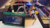
1. yes. the cable i show delivers both 5v and 10v pwm signals for all eight channel.
2. Yes. The Controller works with LDD Controller boards, rapidleds and corulax, and power supplies and mean well LDD drivers .
3. Yes. The Controller has the ability to independently control the photo period for all eight channels simultaneously performing both veg and flower I have been using it for that for some time now..
4. An existing temperature sensor is included as part of the Real Time Clock circuit, which will give ambient room temperatures but not a temperature probe. I leave temperature sensing and controls to other existing environmental sensors on the market. I do not see the temperature probe a necessity for lighting controls, but more for CO2 and AC controls, environmental to me.
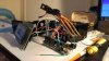
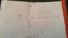
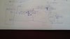
5. Regarding the opto-isolated relay. The relay delivers or cuts power to the Li9ne circuit of the AC side. The Line circuit is interrupted by the PWM signal, either inhibit or prohibit. The relay only has to see the current from a single driver, not multiple drivers. Each relay is used to control each driver. if you have two drivers you need two relays. You do not need two PWM channels to control two relays, just one pwm signal for the both if you want both drivers to behave identically. Each relay never pulls more than the driver demands. mean well recommends no more than six drivers on a 15 amp circuit. That has no impact on the relay. The relay is inline with the current flow of the individual driver. The cable I manufacture provides both a 5v pwm signal for the relay and a 10v pwm signal for the driver dimming. Both are generated from a single arduino pin out. You can control up to 16 relays with 8 pwm signals from terh arduino without any problems. After 16 relays you need a second controller or else get with me to design a larger version that can handle more channels. I have the option to code for many channels. I also have the capability to add more pwm channels by adding additional pwm cards that add 16 chanels at a time. Additional coding is required and can be accomplished, but I have to do the coding for that purpose. if there is a demand for higher channel units I will approach the issue. Until then I am going with the 8 channel model. If you want 24 or more channels you are going to have to hit me up and we are going to have to talk aboput how to get there. An Arduino mega 2560 is the first step, and that cost $49 up from $25 for the Arduino alone plus parts and time. Negotiable.

Future plans, a wifi version and a blue tooth version are both in the works, along with an internet capable version. peace
Vegas
 

Timothypaul26

Well-Known Member
This is the CO2 sensor I have. http://www.co2meter.com/collections/co2-sensors/products/cozir-co2-temperature-humidity-sensor it's not cheap, but there really aren't any cheap CO2 sensors. I chose this one for the temp and humidity features added in. On the arduino forums, Rob Tillaart has come up with a nice serial.print code, I used that and modified it to turn a relay on and off. It's not the best, but it works. Issue is, that there is no night time setting. I am not a strong coder, so it takes me a while to get something working. I am using a CO2 generator (tankless water heater), not a refillable tank.

//
// FILE: CozirDemoSoftwareSerial.ino
// AUTHOR: Rob Tillaart
// VERSION: 0.1.00
// PURPOSE: demo of Cozir lib
// DATE: 2015-jan-17
// URL: http://forum.arduino.cc/index.php?topic=91467.0
//
// Released to the public domain
//

#include <cozir.h>

#include <SoftwareSerial.h>
SoftwareSerial sws(50, 51);


int Relay1 = 12;
int CO2LowThr = 1200;
int CO2HighThr = 1500;


COZIR czr(&sws);

void setup(){
sws.begin(9600);
czr.init();

pinMode(Relay1, OUTPUT);
digitalWrite(Relay1, HIGH);
Serial.begin(9600);
Serial.print("Cozir SoftwareSerial: ");
Serial.println(COZIR_LIB_VERSION);
Serial.println();

delay(1000);
}

void loop(){
float t = czr.Celsius();
float f = czr.Fahrenheit();
float h = czr.Humidity();
uint32_t c = czr.CO2();


Serial.print("Celcius =\t"); Serial.println(t);
Serial.print("Fahrenheit =\t"); Serial.println(f);
Serial.print("Humidity =\t"); Serial.println(h);
Serial.print("CO2 =\t"); Serial.println(c);
Serial.println();

if (c <= CO2LowThr) {
digitalWrite(Relay1, LOW);
Serial.println("CO2 Gen On");
}

if (c >= CO2HighThr) {
digitalWrite(Relay1, HIGH);
Serial.println("CO2 Gen Off");
}
}
 

VegasWinner

Well-Known Member
This is the CO2 sensor I have. http://www.co2meter.com/collections/co2-sensors/products/cozir-co2-temperature-humidity-sensor it's not cheap, but there really aren't any cheap CO2 sensors. I chose this one for the temp and humidity features added in. On the arduino forums, Rob Tillaart has come up with a nice serial.print code, I used that and modified it to turn a relay on and off. It's not the best, but it works. Issue is, that there is no night time setting. I am not a strong coder, so it takes me a while to get something working. I am using a CO2 generator (tankless water heater), not a refillable tank.

//
// FILE: CozirDemoSoftwareSerial.ino
// AUTHOR: Rob Tillaart
// VERSION: 0.1.00
// PURPOSE: demo of Cozir lib
// DATE: 2015-jan-17
// URL: http://forum.arduino.cc/index.php?topic=91467.0
//
// Released to the public domain
//

#include <cozir.h>

#include <SoftwareSerial.h>
SoftwareSerial sws(50, 51);


int Relay1 = 12;
int CO2LowThr = 1200;
int CO2HighThr = 1500;


COZIR czr(&sws);

void setup(){
sws.begin(9600);
czr.init();

pinMode(Relay1, OUTPUT);
digitalWrite(Relay1, HIGH);
Serial.begin(9600);
Serial.print("Cozir SoftwareSerial: ");
Serial.println(COZIR_LIB_VERSION);
Serial.println();

delay(1000);
}

void loop(){
float t = czr.Celsius();
float f = czr.Fahrenheit();
float h = czr.Humidity();
uint32_t c = czr.CO2();


Serial.print("Celcius =\t"); Serial.println(t);
Serial.print("Fahrenheit =\t"); Serial.println(f);
Serial.print("Humidity =\t"); Serial.println(h);
Serial.print("CO2 =\t"); Serial.println(c);
Serial.println();

if (c <= CO2LowThr) {
digitalWrite(Relay1, LOW);
Serial.println("CO2 Gen On");
}

if (c >= CO2HighThr) {
digitalWrite(Relay1, HIGH);
Serial.println("CO2 Gen Off");
}
}
Whatn you want to do is make this a subroutine to call from the loop. use a cycle test, have two times stored curTimeLapse and prevTimelapse to test for how much time has passed and what whether to take action with an if/ else statement, similar to a cycle timer, to tst for need on a timely basis. Establish time barriers for your CO2 operation to take action. How long does it take for CO2 to dissipate to a level below your desired level? that is your upper and lower limit of time monitor. hope that helps. peace
 

Timothypaul26

Well-Known Member
Whatn you want to do is make this a subroutine to call from the loop. use a cycle test, have two times stored curTimeLapse and prevTimelapse to test for how much time has passed and what whether to take action with an if/ else statement, similar to a cycle timer, to tst for need on a timely basis. Establish time barriers for your CO2 operation to take action. How long does it take for CO2 to dissipate to a level below your desired level? that is your upper and lower limit of time monitor. hope that helps. peace
I wish I knew enough about coding to know what all you just said. But yes, something along that line. This was just a code I found and quickly added a way to turn it on and off as required. I haven't actually introduced the co2 generator as of yet, just tested to see if my relay would trigger.
 

VegasWinner

Well-Known Member
I wish I knew enough about coding to know what all you just said. But yes, something along that line. This was just a code I found and quickly added a way to turn it on and off as required. I haven't actually introduced the co2 generator as of yet, just tested to see if my relay would trigger.
I think there is a simpler approach. A basic code snipet to test for CO2 level. set level range, COHIGH, high andCOLOW, low. Set a pwm pin pin A5-A13, setmode( COPIN, OUTPUT_PULLUP); for output_Pullup to activate the pullup resistor of 1.4k and set to HIGH for active, DigitalWrite (COPIN, HIGH);and LOW, DigitalWrite (COPIN, LOW); for inactive. Use a simple cycle timer loop to test for rhe upper and lower bounds of CO2 enrichment. I may build an environmental controller for temp, humidity, CO2, with controls for AC, Humidifier/Dehumidifier, fans, and pressure differentials, using a few sensors for temp, humidity, CO2, and air pressure, a small weather station connected to relays to turn on/off CO2 tanks easy with a relay attached to the nozzle which they make, AC electrical relay to turn on/off, and a electrical relay to turn on/off humidifier/Dehumidifier. Pretty straightforward approach would work quite well. maybe add some wifi or blue tooth capability for a plus. Need to develop App for that. Another project in itself. Anyone do App programming, they have a university site for it, MIT I think. I will look and see if I have some code for CO2.. peace
 

VegasWinner

Well-Known Member
/*
# This Sample code is for display the CO2 sensor output on LCD12864.

# Editor : Phoebe
# Date : 2014.1.15
# Ver : 0.1
# Product: LCD12864 Shield for Arduino
# SKU : DFR0287

# Hardwares:
1. Arduino UNO
2. LCD12864 Shield for Arduino
3. CO2 Sensor

#Steps:
1.Connect the CO2 Sensor to the Analog pin 0
2.Power the UNO board with 7~12V

*/

#include "U8glib.h"

U8GLIB_NHD_C12864 u8g(13, 11, 10, 9, 8); // SPI Com: SCK = 13, MOSI = 11, CS = 10, A0 = 9, RST = 8

#define MG_PIN (1) //define which analog input channel you are going to use
#define BOOL_PIN (2)
#define DC_GAIN (8.5) //define the DC gain of amplifier

#define READ_SAMPLE_INTERVAL (50) //define how many samples you are going to take in normal operation
#define READ_SAMPLE_TIMES (5) //define the time interval(in milisecond) between each samples in

#define ZERO_POINT_VOLTAGE (0.324) //define the output of the sensor in volts when the concentration of CO2 is 400PPM
#define REACTION_VOLTGAE (0.020) //define the voltage drop of the sensor when move the sensor from air into 1000ppm CO2

float CO2Curve[3] = {
2.602,ZERO_POINT_VOLTAGE,(REACTION_VOLTGAE/(2.602-3))};

int percentage;
float volts;

/***************************** LCD12864 display ***********************************
Display the voltage & ppm data on the LCD12864
************************************************************************************/
void draw() {
u8g.setFont(u8g_font_unifont);
u8g.drawStr( 0,11,"Voltage:");
u8g.setPrintPos(70,11);
u8g.print(volts);
u8g.drawStr( 110, 11,"V" );
u8g.drawStr(0,30,"CO2:");
if (percentage == -1) {
u8g.drawStr( 40,30,"<400" );
}
else {
u8g.setPrintPos(40,30);
u8g.print(percentage,DEC);
}
u8g.drawStr( 80,30,"ppm" );
u8g.drawStr( 3, 63,"www.DFRobot.com" );
}
/***************************** MGRead *********************************************
Input: mg_pin - analog channel
Output: output of CO2 Sensor
Remarks: This function reads the output of CO2 Sensor
************************************************************************************/
float MGRead(int mg_pin)
{
int i;
float v=0;

for (i=0;i<READ_SAMPLE_TIMES;i++) {
v += analogRead(mg_pin);
delay(READ_SAMPLE_INTERVAL);
}
v = (v/READ_SAMPLE_TIMES) *5/1024 ;

return v;
}
/***************************** MQGetPercentage **********************************
Input: volts - CO2 Sensor output measured in volts
pcurve - pointer to the curve of the target gas
Output: ppm of the target gas
Remarks: By using the slope and a point of the line. The x(logarithmic value of ppm)
of the line could be derived if y(MG-811 output) is provided. As it is a
logarithmic coordinate, power of 10 is used to convert the result to non-logarithmic
value.
************************************************************************************/
int MGGetPercentage(float volts, float *pcurve)
{
if ((volts/DC_GAIN )>=ZERO_POINT_VOLTAGE) {
return -1;
}
else {
return pow(10, ((volts/DC_GAIN)-pcurve[1])/pcurve[2]+pcurve[0]);
}
}

void setup() {
u8g.setRot180();// rotate screen, if required
}

void loop() {

volts = MGRead(MG_PIN);
percentage = MGGetPercentage(volts,CO2Curve);
u8g.firstPage();
do {
draw();
}
while( u8g.nextPage() );
delay(200);
}
 

VegasWinner

Well-Known Member
Here is a basic ReCycle timer routine
// ----------------variable defintions-------------//
#define OFF_Min = 4; // 5 minutes total time
#define ON_Min = 1; // 1 minute duration on
#define Duration = OFF_Min + ON_Min;
// Pins used to drive timer channels
#define Pin1 = 12; // Pin output for timer 1
#define Pin2 = 13; // Pin output for timer 2
typedef struct {
char* Desc; // Timer Description
int Pin; // pin assigned for output
int OnTime; // On time for timer
int OffTime; // off time for timer
int Duration;// Duration = On + Off
} timerVals_t;

timerVals_t timer[MAX_TIMERS];

timer.Desc[0] = "Hydro");
timer.timerPin = Pin1;
timer.Ontime[0] = ON_Min;
timer.Offtime[0] = OFF_Min;
timer.Duration[0] = ON_Min + OFF_Min;
timer.Desc[1] = "Hydro");
timer.Pin = Pin2;
timer.OnTime3[1] = ON_Min;
timer.OffTime[1] = OFF_Min;
timer.Duration[1] = ON_Min + OFF_Min;
//-------------------
// setup Pins for output for PWM signal to drive relay on/off
Timer timer1(timer[0].Pin,timer[0].On_Min , timer[0].OFF_Min);
Timer timer2(timer[1].Pin,timer[1].On_Min , timer[1].OFF_Min);
// void setup()
{
}

// main loop
void loop () {

timer1.Update();
timer2.Update();


} // end loop
// -----------------timer class function -------------------//
class Timer
{
// Class Member Variables
// These are initialized at startup
int TimerPin; // the number of the timer pin
int OnTime; // minutes of on-time
int OffTime; // minutes of off-time

// These maintain the current state
int TimerState; // ledState used to set the LED
unsigned int oldMinCounter; // will store last time LED was updated
unsigned int minCounter;
// Constructor - creates a Flasher
// and initializes the member variables and state
public:
Timer(int TimerPin, int on, int off)
{
// setup pins for output
pinMode(TimerPin, OUTPUT);

OnTime = on;
OffTime = off;

TimerState = LOW;
oldMinCounter = 0;
}
void Update()
{
// check to see if it's time to change the state of the LED
byte second, minute, hour, dayOfWeek, dayOfMonth, month, year;
getDate(&second, &minute, &hour, dayOfWeek, dayOfMonth, month, year);
minCounter = *hour * 60 + *minute;
if((TimerState == HIGH) && (minCounter - oldMinCounter >= OnTime))
{
TimerState = LOW; // Turn it off
oldMinCounter = minCounter; // Remember the time
digitalWrite(ledPin, ledState); // Update the actual LED
}
else if ((TimerState == LOW) && (minCounter - oldMinCounters >= OffTime))
{
TimerState = HIGH; // turn it on
oldMinCounter = minCounter; // Remember the time
digitalWrite(ledPin, ledState); // Update the actual LED
}
}
};
 

VegasWinner

Well-Known Member
I want to clarify understanding regarding custom coding requirements. The standard GrowGreen comes as advertised. Customization costs will be determined based on needs. The current configuaation cannot be modified beyond having YOUR schedule established upon arrival, so that all you have to do is set the date and time and plug it in. Sorry for any misunderstandings. I shared a simple circuit that generates a 5v pwm signal and a 10v pwm signal. The only problem is the 10v pwm signal is inverted. In order to utilize the signal for dimming, the original pwm signal has to be inverted first so that it is positive orientation upon output through the circuit. This condition makes the pwm signal useless for turning on/off mean well drivers with either a receptacle or a relay. Here is the circuit for those wanting a two component solution to dimming mean well drivers but no on/off functionality. I have devised a new circuit that solves that problem. those with IC background probably know what is next. I went to a company and had a pcb board built for the circuit I will use. The company is easyEDA great for small business activities. ->https://easyeda.com/
peace
10vpwmcircuit.jpg
 

VegasWinner

Well-Known Member
update: ->https://www.youtube.com/channel/UCd9auE6zyUoJoe9rlxoJq6Q
BTW, ask yourself, how would you invert a 10v inverted signal back to it's original orientation? Using a npn transistor and a resistor I was able to invert the signal, with the help of a 9v battery on the collector. So I asked myself, self, how would I invert that signal yet again. I slept on it and woke up thinking a second transistor connected in a similar fashion to the first transistor, should do the trick, but not just any transistor. So I started doing some more research with the thought of reversing the orientation of the signal from negative to positive. I would have to reverse the polarity of the transistor. That's right, I went with a pnp transistor to accommodate the next step of reversing the voltage from -10v to +10v. The question became which transistor to use with so many out there? The solution works, as I have had circuit boards made for the circuit, and will populate the PCB with the appropriate devices and use them to create both 5v and 10v pwm signals simultaneously for the GrowGreen LED Controller.
peace
Vegas
 

VegasWinner

Well-Known Member
Looking at the circuit I developed I added a 1k resistor to the collector tied that to the base of an n2907a pnp transistor a companion to the 2n2222a transistor. Connect 10v to the emitter of the 2907a and tie the collector to dim+ and gnd to dim- connecting a 1k resistor across the dim + - connectors to act as a pulldown resistor. This will invert the10v signal back to positive 10v pwm signal. I will post a circuit later. There are also other ways to accomplish this task. Peace Vegas
 

VegasWinner

Well-Known Member
Here is the circuit that works . It takes 5v pwm from the Arduino Uno and drives it thru the 2n2222a transistor inverting the signal to -10v pwm, run thru another 1k resistor to the base of the companion 2n2907a pnp transistor with the collector tied to Dim+ and the Emitter tied to 10v will create a 10v pwm signal. you need either a 9v battery, 10v wall wort, and place a rsistor across Dim= and Dim- of 1k to act as a pulldown resistor to the MW driver. It works. I alsio have other solutions as well. This one requries a pcb board to tie 5 devices two transistors npn and pnp and three 1k resistors for the circuit. peace
Vegashighlow_side switching.jpg
 

VegasWinner

Well-Known Member
A little update for folks.
First we have an arduino based industrial PLC applications using relays, and pwm drivers we have been looking at here. It is 45 minuters long, but you can fast forward to the parts you find interesting.
Second. PWM dimming for HLG drivers. Thee is a non-DIY solution for you folks out there, that are interested. here is a the simplest and cheapest solution per channel available on ebay here
http://www.ebay.com/itm/262623559315?_trksid=p2060353.m1438.l2649&ssPageName=STRK:MEBIDX:IT This board will convert your 5vdc pwm signal to a 10vdc pwm signal. enjoy. peace
Vegas
 

Timothypaul26

Well-Known Member
Here is a soil moisture sensor connected to a relay that turns on a pump to water plant. http://www.ebay.com/itm/Soil-Humidity-Relay-Module-Sensor-Garden-Moisture-Detector-LM393-Chip-Indicator-/331716894429?hash=item4d3bde1edd:g:YbYAAOxyUrZSoZi1 only needs a 5v signal for power, and set moisture to level desired. set it and forget it. peace
Vegas
Only problem with these type of sensors, is that they are meant for prototyping, and will corrode quickly and be useless. There are some diy builds out there for galvanized nails, they have the same issue. Ive built one using some stainless screws, haven't had a chance to test it. I did try the galvanized nail sensor and worked well for a few days, then was so corroded it was no longer accurate. There are some newer, humidity style sensors that might work, but are very expensive ~$50 each
 
Top