On/Off functin for meanwell HLG style drivers using dimming and arduino

VegasWinner

Well-Known Member
I was hoping you simply made a mistake, but by now I have to agree with ya bongo :dunce::wall:

Your switch is on the low side of the circuit since it's between the load and ground. That's which makes it a "low side switch". That you don't even understand basics like that explains why you think you need a 10V source though.
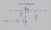
Explaining to someone not reading is insane. Try dimming without a 10v power source. Theory only works when smoking. Try dimming like you say if it is so easy why has no one done it commercially yet. Hmmm. Say what you want a 10v source makes it a high side switch. Yes you need. 10v unless you like dimming backwards. Try actual proof instead of agreeing on a theory.
 

VegasWinner

Well-Known Member
hey vegas, can you make the growgreen dim in response to temperature? for example:

-dimming light intensity to maintain temperature at optimum on hot days when fans arent enough
-for those in cold climates, throwing on additional lights when needed to maintain temperature (as opposed to a heater- throw more light in there)
-as a safety when exhaust fan goes down- dimming lights as opposed to killing them entirely (to maintain photoperiod)
Dimming with respect to temps can be accomplished with some thought. Peace
 

VegasWinner

Well-Known Member
I was hoping you simply made a mistake, but by now I have to agree with ya bongo :dunce::wall:

Your switch is on the low side of the circuit since it's between the load and ground. That's which makes it a "low side switch". That you don't even understand basics like that explains why you think you need a 10V source though.
You should move on when you lack any actual efforts other than smoking weed and theorizing. Peace
Namaste dont hurt you head trying to understand what is in front of you.
 

VegasWinner

Well-Known Member
I was hoping you simply made a mistake, but by now I have to agree with ya bongo :dunce::wall:

Your switch is on the low side of the circuit since it's between the load and ground. That's which makes it a "low side switch". That you don't even understand basics like that explains why you think you need a 10V source though.
Show me. Build the circuit, using an arduino output 5v into a circuit and into a meanwell HLG style driver 10v dimmer signal in syn not inverted. Please show me how to do this. If not stop theorizing and start doing some actual work and stop confusing people with your theories if you could do it so simple with just a low side switch it would have been done. I already did that and it reverses the polarity of the signal. Any npn transistor can do that. the trick is to invert it in sync with the original signal. show me instead of talking and smoking. thank-you
namaste
 

VegasWinner

Well-Known Member
If people have any further questions you can pm me. I am not going to continue to argue with people here on this thread. Have a great day.
Namaste
 

wietefras

Well-Known Member
I have been using pwm dimmers for years. Without extra 10V.

Pro tip: If you need to invert the signal, you can simply invert the PWM signal from the Arduino .
 

VegasWinner

Well-Known Member
I have been getting so0me questions regarding power supply for the 5v relays. I would recommend this one for a build. You can include the 5v 5A power supply with the drivers connected at the WAGO connection and provide 5v power to your fixture. I you have multiple fixtures, you can mount these for like $6 a piece or you can daisy-chain the relays with one power supply. Whichever way you loike, both work equally well, and have been tested.
power supply-> http://www.ebay.com/itm/350944322084?_trksid=p2057872.m2749.l2649&ssPageName=STRK:MEBIDX:IT
wall wort-> http://www.ebay.com/itm/ENG-5V-2-0A-AC-DC-WALL-WART-POWER-SUPPLY-ADAPTER-CORD-MOD-EPAS-101WU-05-/272419270201?hash=item3f6d742e39:g:TG8AAOSwxKtYB2FJ
namaste
 

VegasWinner

Well-Known Member
A little update:
I revised the case and removed the front legs and now it is a cube. see. B ut wait there is more. I have been working on an automation lighting system using openHab. Here are some screen shots. enjoy.
 

Attachments

VegasWinner

Well-Known Member
I'll need that soon :)
I am using an RPI3 and it has wifi and bluetooth. It also runs the openHAB program. I have been working on this for some time now. The last part is to set up and test the relays for turning lights on/off on schedule. The entire program will run as an ios/android app also.
 

Gromax 3590B

Active Member
Is that rpi stable enough? I did several projects with the pi and most of the time the pi freezes after a few weeks. It looks nice.
 

Gromax 3590B

Active Member
I am using an RPI3 and it has wifi and bluetooth. It also runs the openHAB program. I have been working on this for some time now. The last part is to set up and test the relays for turning lights on/off on schedule. The entire program will run as an ios/android app also.
He is using arduino not a pi look at the title
I do not only read the title but i read the whole thread.

He is using a RPI3. bongsmilie
 
Last edited:

disbeverk

Well-Known Member
Is that rpi stable enough? I did several projects with the pi and most of the time the pi freezes after a few weeks. It looks nice.
I've been running a pi2 as the controller for my aero pumps for over a year and I've been very impressed with the stability. Only hiccup I've had was a cheap memory card going bad.
 
Top