6/12 bud

YaK

just some guy
So we need to adjust its orbit?? Count me and my atomic discombobulator (patent pending) in...
lol. maybe we can take the rocket schematics that someone googled, buy some solid rocket fuel on ebay, and attach the rockets to the planet to adjust it's orbit.

The planet is like... 180 light years away, so I need to do some googling to figure out how to get there with said rockets, and slave alien labor for the installation.

This could work!
 

fdd2blk

Well-Known Member
this is like rubics cube shit. 24 x 3 = 72 , which divided by 18 = 4

So... maybe you can do it by daisy chaining 3 timers. I pounded about 5 keystones and had that same thought, timer to a timer to a timer, then I gave up and figured it'd just be easier to spend the 300 bones for a digi.

I'd still like to know though if it's possible to put timers together, if so, you'd be able to make one for less than 30 dollars.

i recently bought a digital "sprinkler timer" from home depot. it a really nice one. it's is set-up in weeks mode. Sunday thru Saturday. i think i can set 30 different on/off times. i paid 20 s0mething dollars for it. they had a shelf full.


nobody will do this. :-P:clap:
 

winkdogg420

Well-Known Member
you could have one timer running 18 on 6 off to create the cycle. a timer plugged into that set to 6on 12off when it finishes its 6/12 the other timer will kick it off for 6 hours before it runs another 6on 12 off ,would this work???
 

born2killspam

Well-Known Member
I did some preliminary work on an adjustable timer.. This isn't a finished work as of yet, I'm just putting it up for discussion..
Basically the circuit operation is ICs 1&2 + adjacent components create 1 minute pulses by counting the crystal oscillations.. These pulses are further counted by ICs 4&5 in the centre.. (Currently ICs 4&5 are wired for 24hr [1440min] days before resetting, but thats easily changed to 1080 minutes or whatever..)
ICs 6&7 on the left control the delays before powerup, and powerdown after initial startup by resetting ICs 4&5 respectively.. IC4 (top centre) turns on the relay once/day through the flipflop, IC5 below turns it off once/day.. (A day is defined by how many minutes IC's 4&5 are wired for..)
(Also note that ICs 6&7 are currently wired for 1440 minutes in this picture which is nonsensical)
So the circuit is powered up.. Lets say IC6 is wired for 60min, and IC7 for 780min.. After 60 minutes it will reset IC4's count, and turn on the relay.. IC4 will keep turning it on at the same time every day period.. 6 hours later IC7 will reset IC5's count and turn off the relay.. It will keep turning it off every day period at the same time..
ICs 6&7 are just one shots, they're there to reset 4&5 at the proper time on the first cycle only, and after that they're synced to the day rythm..
It runs off 9VDC, the battery is just there to keep its time synced with reality in the case of a power outage..
I adapted this from a circuit I downloaded ages ago..
 

Attachments

winkdogg420

Well-Known Member
i could prob get a breadboard and get all this stuff together but wouldnt it be easier...(start pounding head now) just to take a single ic and change it to 1080 clicks or whatever then just have that trip a relay. again you are the expert here no doubt im just trying to simplify the build for myself. im not sure how many "things" the mentioned ic's can do??

thanks winkdogg!


I did some preliminary work on an adjustable timer.. This isn't a finished work as of yet, I'm just putting it up for discussion..
Basically the circuit operation is ICs 1&2 + adjacent components create 1 minute pulses by counting the crystal oscillations.. These pulses are further counted by ICs 4&5 in the centre.. (Currently ICs 4&5 are wired for 24hr [1440min] days before resetting, but thats easily changed to 1080 minutes or whatever..)
ICs 6&7 on the left control the delays before powerup, and powerdown after initial startup by resetting ICs 4&5 respectively.. IC4 (top centre) turns on the relay once/day through the flipflop, IC5 below turns it off once/day.. (A day is defined by how many minutes IC's 4&5 are wired for..)
(Also note that ICs 6&7 are currently wired for 1440 minutes in this picture which is nonsensical)
So the circuit is powered up.. Lets say IC6 is wired for 60min, and IC7 for 780min.. After 60 minutes it will reset IC4's count, and turn on the relay.. IC4 will keep turning it on at the same time every day period.. 6 hours later IC7 will reset IC5's count and turn off the relay.. It will keep turning it off every day period at the same time..
ICs 6&7 are just one shots, they're there to reset 4&5 at the proper time on the first cycle only, and after that they're synced to the day rythm..
It runs off 9VDC, the battery is just there to keep its time synced with reality in the case of a power outage..
I adapted this from a circuit I downloaded ages ago..
 

born2killspam

Well-Known Member
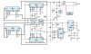
Well the thing is, crystals are the only trustworthy way to keep time, and they run at a pretty high frequency so they need to be frequency_divided with the 4040 counters.. Even timer chips need counters to get a period longer than a few seconds..
So we do need the crystal, we need the counters, and we need the flip-flop since our signals are pulses, and they hold their value once set..
I suppose IC6 could be eliminated, and altered so that the relay is powered immediately when the circuit is started, but we still need IC7 to set the turn off time.. It might be possible to eliminate a counter in the crystal area, but with both of them the pulses are calibrated to 1 minute which really makes usage easier..
There are other ways to cascade the counters.. eg, one to measure day length with one to measure on-time slaved after it, but this opposable setup is probably roughly as simple as any method would be.. It really isn't that complicated as far as circuits go..
If you're confused about how the counters reset themselves, notice their outputs are all tied to 9V, and to the reset pin.. when all the tied outputs are high, they stop sinking that 9V, so it triggers the reset and it starts counting again..
 

winkdogg420

Well-Known Member
Ive been out of high school for 13 years and that was the last time i did any serious circut building:( i guess im a bit rusty i will grab ic's for dummies (not kidding) and see if i can get a better understanding of whats going on. Now even if i dont grow this way i still want to build the timer just to get my skills sharpened! Are most of these parts standard stuff?? Like radio shack ? Im not sure what chips they stock anymore i worked there years ago and we had tons of parts i even took some training coarses for them but none of it stuck..


well the thing is, crystals are the only trustworthy way to keep time, and they run at a pretty high frequency so they need to be frequency_divided with the 4040 counters.. Even timer chips need counters to get a period longer than a few seconds..
So we do need the crystal, we need the counters, and we need the flip-flop since our signals are pulses, and they hold their value once set..
I suppose ic6 could be eliminated, and altered so that the relay is powered immediately when the circuit is started, but we still need ic7 to set the turn off time.. It might be possible to eliminate a counter in the crystal area, but with both of them the pulses are calibrated to 1 minute which really makes usage easier..
There are other ways to cascade the counters.. Eg, one to measure day length with one to measure on-time slaved after it, but this opposable setup is probably roughly as simple as any method would be.. It really isn't that complicated as far as circuits go..
If you're confused about how the counters reset themselves, notice their outputs are all tied to 9v, and to the reset pin.. When all the tied outputs are high, they stop sinking that 9v, so it triggers the reset and it starts counting again..
 

winkdogg420

Well-Known Member
i will let you know when im near build stage i need to do some serious re-research i will go to the library tomorrow i seem to absorb more from books then the net. anything you can think i should check-out of the library?

Its an all around useful project.. I can answer specifics..
 

born2killspam

Well-Known Member
I'm gonna start up a thread on this in the DIY section sometime today.. It'll keep this thread cleaner, and this timer has alot of applications for cycling anything on a non 24hr basis.. (Like fans/pumps etc)..
 

weedyoo

Well-Known Member
I'm gonna start up a thread on this in the DIY section sometime today.. It'll keep this thread cleaner, and this timer has alot of applications for cycling anything on a non 24hr basis.. (Like fans/pumps etc)..
wow this is above my pay grade hahah i have no clue what is going on

thanks you guys this is how you learn some thing new.
 

born2killspam

Well-Known Member
Its actually a really simple circuit for its size.. Each area of the schematic does a stage..
ICs 1&2 and the components near them create the one minute clock, IC's 4&5 count these minutes and each trigger the relay once per day cycle.. (IC4 turns on the relay, IC5 turns it off).. ICs 6&7 just control when the relay gets triggered by counting up to their set delays, then resetting the counters in ICs 4&5 respectively (on the first cycle only).. Basically when the relay is supposed to come one, IC4 gets reset to 0.. It then counts as many minutes as are in a day cycle and then turns it on again.. Same thing with the off switch, IC7 waits until the relay is supposed to go off, then resets IC5 so that its sync'd to keep turning off at the same time each day.. In the original circuit, ICs 6&7 did not exist.. It was set up with normally closed push switches that manually got pressed the first day at the proper on/off times, then IC's 4&5 just repeated that process every day cycle.. (Again a day cycle is as many minutes as ICs 4&5 are set to count before resetting)..
I just noticed, I think I need a few more diodes on the outputs of ICs 6&7 going to the resets, and pins 1&2 of the IC3 4013 flip-flop..
BTW, the parts for this are probably $10-20.. Chip prices can vary dramatically depending on supplier.. Even paying top dollar though it probably won't cost as much as any standard timer walmart sells..
 

winkdogg420

Well-Known Member
i will start looking for the parts and find the new thread!


Its actually a really simple circuit for its size.. Each area of the schematic does a stage..
ICs 1&2 and the components near them create the one minute clock, IC's 4&5 count these minutes and each trigger the relay once per day cycle.. (IC4 turns on the relay, IC5 turns it off).. ICs 6&7 just control when the relay gets triggered by counting up to their set delays, then resetting the counters in ICs 4&5 respectively (on the first cycle only).. Basically when the relay is supposed to come one, IC4 gets reset to 0.. It then counts as many minutes as are in a day cycle and then turns it on again.. Same thing with the off switch, IC7 waits until the relay is supposed to go off, then resets IC5 so that its sync'd to keep turning off at the same time each day.. In the original circuit, ICs 6&7 did not exist.. It was set up with normally closed push switches that manually got pressed the first day at the proper on/off times, then IC's 4&5 just repeated that process every day cycle.. (Again a day cycle is as many minutes as ICs 4&5 are set to count before resetting) I just noticed, I think I need a few more diodes on the outputs of ICs 6&7 going to the resets, and pins 1&2 of the IC3 4013 flip-flop..
BTW, the parts for this are probably $10-20.. Chip prices can vary dramatically depending on supplier.. Even paying top dollar though it probably won't cost as much as any standard timer walmart sells..
 

boston george 54

Well-Known Member
i recently bought a digital "sprinkler timer" from home depot. it a really nice one. it's is set-up in weeks mode. Sunday thru Saturday. i think i can set 30 different on/off times. i paid 20 s0mething dollars for it. they had a shelf full.


nobody will do this. :-P:clap:

nobodys gonna do it :finger:
 

born2killspam

Well-Known Member
I got 2 similar timers at walmart a few years ago for $30.. They have 14 programs (14 on times, and 14 off times).. Are programmable on a daily/weekly schedule, have a countdown timer function, a random function, are easily over-ridable without messing up the program, has a battery backup, and even has a button to easily adjust for daylight savings..:) They're waaay better than my project, but I can't find them in Walmart anymore..
They are:
"Intermatic 7 day Timer Model DT 17"..
 

fdd2blk

Well-Known Member
I got 2 similar timers at walmart a few years ago for $30.. They have 14 programs (14 on times, and 14 off times).. Are programmable on a daily/weekly schedule, have a countdown timer function, a random function, are easily over-ridable without messing up the program, has a battery backup, and even has a button to easily adjust for daylight savings..:) They're waaay better than my project, but I can't find them in Walmart anymore..
They are:
"Intermatic 7 day Timer Model DT 17"..


that's the same thing i'm using right now. i'm not sure if it's the "exact" same, but it sounds like it. my lights are out. i'll check later.

i found mine at home depot in the timer isle. they call it an "outside sprinkler timer". :clap:

even if you had to restart every 7 days it wouldn't be so bad. or you could do the math. :-P
 
Top