GD-SDS .Short notice / update..

Fonzarelli

Active Member
Isnt it great...you can actually see what the plants are doing...unlike these all red/blue panels....Booo! :D

Looking lovely Stardust. :)
https://www.rollitup.org/led-other-lighting/636502-200w-solarflare-california-lightworks-bagseed.html

The CLW panels are pretty much R:B with only a few WHITE LEDs. You can tell by looking at their "SPDs." Mostly Deep Red LEDs, some Blue and only a few White. Unless anyone has the exact specs. This guy is getting REALLY nice growth with the panel. Something tells me there is more to it. When I see White Only grows the plants look a little less healthy. Probably the lack of deep/far red and some extra blue. That % chart I found shows the best ratio to be around 10%Blue:10%Green%:70%Red. This means only a few Whites would be used. Lets say, 1 blue, 3 whites, 21 reds. Seems like way more RED than a plant could handle. Something like that? Works in theory, but I haven't had any luck growing with LEDs yet. I think I had WAY more Red than the plants can handle.

Another aspect that may have been the failure part of it in the panels I made was that I was driving around 200w of leds and I am pretty dang sure that that much power when it's mostly RED LEDs is going to cause over-saturation in the leaf. I think red:blue (mainly) led panels work best when they are low wattage. But it's all wondering, I can't say much for LEDs at this point, hopefully soon enough.
 

stardustsailor

Well-Known Member
What do you think is causing that slight wrinkle texture is on the bottom and side fan leaves? Seems like it would be a certain wavelength doing that, but maybe nute?

Could you please tell me what LEDs are used on the MIDDLE panel? Please speak in English, because I do not understand the C3P0 talk or whatever that is. As in Luxeon NW 3000k or whatever they are. Looks to be a mixture of warms and neutrals, but I don't understand exactly what you typed as to what LEDs were used on the MIDDLE panel.

What LEDs are used on the SIDE panels? Same English if you don't mind. Want to get an idea of the type of spectrum you are running.

And a question for whomever can answer: I run all my LEDs in series on a constant current driver. Can I also run the PC cooling fan in series with the LEDs? Is it possible? I use a 12v cooling fan that runs around 700mA. Typically I power them on a separate ac/dc adapter that is constant voltage. I don't quite understand what requirements a dc fan has for instance, in order to dim LEDs you can change the current(yes I already know about PWM) which can effect the peak wavelength, but it does work for dimming.

As for the cooling fan, what controls fan speed, Amps or Volts? If the fan requirements are lower than 700mA(my LEDs driver) will the fan speed increase? Something I haven't figured out yet.
Ok Fonz .....

1 ) I'm really having that query myself ....
Those wrinkled fan leaves ,are pretty common in my grows ,even from when I was growing with HPS ....

Maybe are caused :

-By a slight pH unbalance ...
( I doubt that they 're caused from a nutrient disorder ,like i.e. Nitrogen ,in form of Ammonium )
-Maybe caused by not moving -oscillating fan air current ?
-Maybe light-burns ,especially from a certain wl ? (blue ain't for sure ... ) ..It seems that are caused from light ...


2 ) Middle panel has ( total ) :
12 x Neutral Whites 4000 K
( with RED & green phosphor aka HIGH CRI - around 92-95 - leds ) &
24 x Warm Whites 3000 K ( with amber phosphor aka MID CRI - around 80-85 - leds ) ....

( I do not totally agree with you ,when you say "yellow light is useless for plants ,or plants ' hate ' yellow light .
My opinion is way opposite ..Without it plants ,will not reach to their genetic potential .... )

spectra LCW Cx7P_CC.jpgec 3000 K.jpg......

(middle panel's led spectrums @ average.. = From first pic the cyan colored line for the NW
& from second pic the green line for the WW ..)


Other two panels ,have each, in total :
12 x 660 nm hyper/deep reds &
24 x Warm white 2700 K ( green & red phosphor HIGH CRI 95 ) .
(In first pic's -above- the yellow spectral curve .... ) .....

So .....

More simply put :

The middle panel has a broad main wl emission curve peaking at ~610 nm ...(From 24x WW 3000K CRI 80 leds ) ..
It has two secondary "bumps-peaks " at ~ 550 nm and ~ 630-640 nm (From 12x NW 4000K CRI 95 leds ) ..
Also there is present a peak at blue ~440-445 nm (From all 36 leds used ...) .At ~ 10-20% of total output flux ...Of the panel ...
(Depending on driving current ..)

Rest two boxes/panels present a main peak at 640-660 nm ...(mainly from 12x hyper red leds .Which are powerful / really efficient ..)
Only to "smoothly " diminish towards blue ,with a nice "slope" ...
( from 24 x WW 2700 K CRI 95, which peak at ~630 -640 nm and 'slope down' smoothly towards their small blue peak at ~445 nm )
Those two panels , also provide some Far red wls (700-750 nm ) .


Thing is that all work at same time ....
Blending-in quite wide range of different "blends "of light , regarding spectrum,power & incident angle -their output light ,through the dimming function,that all have ...

It is a "full 400-750 nm spectrum " light -rather inclined towards red wls -,
which can shift -quite greatly-from "slightly warm white light " to "really heavily red enhanced -white light ..
Become kinda pinkish to human vision ..

Total amount of blue wls ,when all leds run at max is about 5-8% ...
Approx same with a HPS ,more or less ...

-----------------------------------------------------------------------------------------

As for the fan part ......

Since Fan has an operating current @700 mA( !!!! RU sure ? that's pretty much !!! ),
then yes you can drive the fan in series with leds ,using a CC driver .....

BUT ...

Fan will 'steal' from driver ~ 12 Volts ....

-If your driver can provide that extra 12 Volts for the Fan ,no problem ....

-If your driver has a max voltage output i.e. 60 Volts and already drives a series of leds ,
with a total voltage drop ~ 58 volts ,no fan can not be powered from driver ...
Driver has only ~ 2 volts ,to ' spare ' at that case ....
...

Leds CC driver can be either analog dimmed or digitally .
( Through a Pulse Width Modulation 'signal' -aka voltage ) ...


Fans the same ...
Analog dimming through adjusting their operating voltage(they all do have a range ...).

This way offers limited range of control ....I.e from 1000 rpm up to 3000 rpm ....


Or through PWM some fans ,can be dimmed/controlled digitally ,
like computers do with their CPU fan..

That way offers maximum & precise control of fan's RPM .....

Fan speed is -analog- controlled by Voltage if you use a CV power regulator ...
(with adjustable output voltage of course .... )

At i.e. 9 volts fan will work at 2000 rpm and 400 mAmperes current will pass ...(will be "drawn" by the fan ,more correctly... )
At 12 volts ,fan will work at 3000 rpm and 700mA current will pass .
AT 15 Volts ,fan will work at 3800 rpm and 900mA current will pass .

at 20 volts ,fan will work at 4000 rpm and 1200mA current will pass .
Will overheat the wiring at motors coils ....
Their Insulation will melt .....
Fan will "burn " and stop working for good ...

If you dim the fan with a CC driver :

At ~400mA ,fan will work at 2000 rpm and will 'drop' the voltage ~ 9 volts ...
At ~700mA ,fan will work at 3000 rpm and will 'drop' the voltage ~ 12 volts ...
At ~900mA ,fan will work at 3800 rpm and will 'drop' the voltage ~ 15 volts ...

And ...

At ~1200mA ,fan will work at 4000 rpm and will 'drop' the voltage ~ 20volts ...
Work for a minute or so and get fried afterwards ....


Fans ,resemble more of a ' resistor ' ..
Not of a 'diode',like leds are .....

Moreover ....

...It's a rather bad idea to mix fans & leds ,at the same circuit ....
Fans contain coils and (moving ) magnets ....
Thus, fans also do generate back, a counter -current & voltage to the operating ones ...

All electric motors are at same time power generators ..
And vice versa ....
They are just constructed differently ,in order to be more efficient in either turning or producing electric energy ,respectively ...
So,things can mess up ,pretty easy ,with a fan in series with the leds ....


Funny thing :

.......Leds use electricity to produce light ....

Well ...They kinda also work backwards ...
Absorbing light ,they produce electricity ....
But for sure are not the cheapest type of ..photovoltaic devices ....
 

stardustsailor

Well-Known Member
https://www.rollitup.org/led-other-lighting/636502-200w-solarflare-california-lightworks-bagseed.html

The CLW panels are pretty much R:B with only a few WHITE LEDs. You can tell by looking at their "SPDs." Mostly Deep Red LEDs, some Blue and only a few White. Unless anyone has the exact specs. This guy is getting REALLY nice growth with the panel. Something tells me there is more to it. When I see White Only grows the plants look a little less healthy. Probably the lack of deep/far red and some extra blue. That % chart I found shows the best ratio to be around 10%Blue:10%Green%:70%Red. This means only a few Whites would be used. Lets say, 1 blue, 3 whites, 21 reds. Seems like way more RED than a plant could handle. Something like that? Works in theory, but I haven't had any luck growing with LEDs yet. I think I had WAY more Red than the plants can handle.

Another aspect that may have been the failure part of it in the panels I made was that I was driving around 200w of leds and I am pretty dang sure that that much power when it's mostly RED LEDs is going to cause over-saturation in the leaf. I think red:blue (mainly) led panels work best when they are low wattage. But it's all wondering, I can't say much for LEDs at this point, hopefully soon enough.

Think this :

Chlorophyll A does have a peak absorption at ~662 nm ,but still absorbs photons at ~560 nm (Amber ) ....

Take a plant and radiate it with monochromatic radiation of 100 W flux , at ~662 nm .....

There are no other photons for ChA to absorb .Only the ones that absorbs most .


Take another plant now and radiate it with red radiation of 100 W flux ,as before but not monochromatic ....

'Flat peak " from 560 nm up to 660 nm .....

Lot less 662 nm photons than before ,as power of 100 Watts now is "distributed " all the way from 560 up to 660 nm ,equally ....
So lot less photons at 662 nm ,than first case ...But now there are other photons .....


Which of two cases you think ,is the one ,that the plant will thrive and at which case plant will be stunted ?

Tip : Energy = Power x time .

Photosystems do have a "max load " of operation ..
Above that ,they cease working or even get damaged ......


So .....

( Now ,you probably understand ,why amber & yellow light is needed ..-at photosynthesis ,at least .....
They "ease " the photosystems .......
Do not allow the chlorophylls to "overdrive " the rest of photosynthetic apparatus ...)

A living cell is not a machine ,that can work at it's max load-absorption-efficiency -etc for prolonged time
Or solely like that ........Working only at max !!!!
Let us do not forget that .....'Cause ChA might have a max absorption peak at 662 nm ,doesn't necessarily means ,
that : "ok guys ,let's blast them with deep red light ...Make the best out of them .....Give'em the Max efficient light " ,
is the right thing to do ....

No ...I'm afraid it does not work that way ,with living cells,tissues and organisms .....)
 

stardustsailor

Well-Known Member
I guess what I'm trying to say is this :

Take things from start....

Regarding the Amber & red range of light .....

At natural environments -at spring-summer-autumn seasons - daylight begins with poor content in deep reds ( > ~640 nm ) ..
Later as noon (Sun's zenith position at sky ) approaches ,deep reds start to dominate ...Peaking at noon ...
And then start to decrease in power -in a more "smoother" rate than was the "increasing" during the morning hours .....

So Chlorophyls start really to peak their deep red absorption close to noon ,at noon and some time afterwards .....

Deep red photons are abundant ,only for limited time ,per dia (per day ... ) ..

While amber/yellow/amber-red photons are present at higher power levels ,most of day .......Still,following ,more-or less ,same power profile of deep reds ..
Increase-peak ,at noon -decrease .....


At a controlled environment ,light power usually is stable and does not follow same power profile as the sunlight ....
More like ..." on & off "....


HPS has a lot of yellow/amber light and less red & deep red .......

Plants can be radiated for prolonged time ,under stable power profile ....

HPS ,will not "overdrive " PS systems of a plant ,from the first hour of radiation...


What has not been tried is this .....

Blast the plants with 660 nm deep red light for ~ 2hours(for example ) ...
1 hour darkness ...For the PS systems to recover ...
Re-blast ,again for ~ 2hours ....
Again let them for 1 hour in darkness to recover ,from their max load operation ....
And so on ....

20/4 vegging cycle,for example ?

5 hours under light heavy in Deep reds ..
1 Hour darkness..
5 hours under light heavy in Deep reds ..
1 Hour darkness.
5 hours under light heavy in Deep reds ..
1 Hour darkness.
5 hours under light heavy in Deep reds ..
1 Hour darkness.
..
And so on ....


Maybe ,that is a way which makes the best of 662 nm peak of ChA ...
Plants will not get photo-saturated (as also photo-inhibited ) that easy ,
as they'll have "breaks" between the 660 nm radiation...
Allowing for PS systems to recover ...

Just an idea .....

Who knows ...
 

PetFlora

Well-Known Member
^^ The short amount of ~660 per day from sun is one of the reasons why I have long promoted the idea of 660+ being on a separate o/o circuit/timer. Without separate control, probably better off without 660 range, unless in tiny amounts (~ <10%)
 

stardustsailor

Well-Known Member
^^ The amount of ~660 per day from sun is one of the reasons why I have long promoted the idea of 660+ being on a separate o/o circuit/timer. Without separate control, probably better off without 660 range, unless in tiny amounts (~ <10%)

Well ,yes ,a pretty nice thought ...

I dealt with 'it' by other means ....

(introducing plenty of green & yellow wls as "counteractants " and lots of Ambers/reds .Plus a dimming function )

As for the 10% ...

Well I'm still not quite sure ,but I trust it is needed -way- more of 10% of overall light flux ,
for in use on a stable power profile lasting 12 hours ..

(During flowering ,where deep reds are most beneficial ... -Lots of photons along with the fact that new leaf production has greatly diminished ....
At that 'point' ,deep red wls ,do provide 'pure energy ',to the already 'mature' leaf canopy ... )

For flowering I tend towards using 60-70% of power at the region 600-700 nm ....
From that ,more than half is at 640-660 nm range ...

So I'd go for a 30-40 % of overall light flux ,at the 640-660 nm range .
( Only during flowering,though ...)
 

PetFlora

Well-Known Member
Let me clarify, when one has >50% in 600-630, then ~ 10% 660, and of course the other spectrums ~ in balance
 

stardustsailor

Well-Known Member
Pet ,I still remain unsure about it ....
Anyway ....

While many of the 'theories' presented here at this forum (by me and few others ) ,may not be 'appealing' to some others ..
Or even disliked and characterized as BS ....... Or doubted ,whatsoever ....

For these matters I tend not to listen to what people have to say ....

Plants are the ones ,that have a pretty 'solid' opinion about ,those issues ....
Those are the ones I trust ,mostly ....

So ...Few hours later ,from previous pics ....

P5206581.JPGP5206582.JPGP5206583.JPG.....

I think they find these "theories " ,quite ' fascinating ' ...
( -GD-SDS system's spectrum is build uppon those 'crazy' theories ..)
'Enlightening '....I may say ...
At least ,up to now ,they seem to do so ....
 

stardustsailor

Well-Known Member
Still I feel there's an 'impact' at the plants .
Those two first weeks of vegetative stage were pretty crucial ...
And then the system was not fully complete -ready to work ....

( Though it was a chance to 'notice' pretty interesting things .... Plenty ... _)

So ,I think there's going to be 'something' of a negative somewhat impact ....

Anyway ...

The next grow with the system ,is going to be really interesting ....

I'm going to test some new time schedules,with leds ..

Veg with 10 hours light-2 hours off -10 hours on -2 hours off ,cycle per day ..
And flower with 6 hours on -6 off -6 on - 6 off ,cycle per day .....

I just want to check something ....
One of the 'theories' ...

(Probably next grow is going to be with 4x feminised Arjans Haze ,as 'test' plants ...)
.....

Anyway ...
Right now ....
I'm curious about the flowering of the present grow ....
....
There's couple of 'questions' I've , that need to be answered ASAP , by those plants ....
 

stardustsailor

Well-Known Member
Guod..

There's also an additional issue with digital amperemeters and the system ...

The MeanWell DC PSU ,through a pot ,can have an adjustable range of output voltage from ~39 Volts up to ~57 Volts ....

That's what it is used for the analog control of fan's RPM ,right now ...

So digital amperemeters with operating voltage ~48 Volts DC ,will severely ' limit ' the fan's working range .....
Mainly close to 48 Volts ... +/- ~ 1-2 volts ....


I do have to find some compact analog amperemeters ....
 

Fonzarelli

Active Member
Thanks for clearing up the fan issue. I will keep them on a separate driver.

The CLW 200w LED panel is mainly a red:blue panel that has mostly 660nm LEDs and the plant is soaking it up with no problem.

I agree that all 660 is harsh, but some plants don't seem to mind it according to other growers. I have yet to see a plant successfully growing under ANY LEDs with my own eyes lol.

I'm starting a new panel that hopefully will work. Lots of blue :).

I've seen that wrinkly type of growth before on someone else's grow when they were using T5's. My guess is nute overdose of some sort, maybe Nitrogen overdose? Also could be humidity levels. What's your RH at?
 

stardustsailor

Well-Known Member
Now .....
I've to get one of these .....

The 'poor man's reflow oven " ...
Puhui T 962 / 962A ..

( The T 962 C is really nice also .... )

http://www.ebay.com/itm/new-T962-Infrared-SMD-BGA-IC-Heater-Reflow-Oven-18X23-5CM-/271195005806?pt=LH_DefaultDomain_0&hash=item3f247b636e

And "upgrade" it with a PID* microcontroller ...

http://www.ebay.com/itm/Reflow-Oven-Controller-PID-Ramp-rate-fits-T962-and-T962A-ovens-better-control-/190842334813?pt=LH_DefaultDomain_3&hash=item2c6f16ee5d


*PID microcontroller :

The Reflow Process

A reflow oven is used to reflow solder surface mount components onto a Printed Circuit Board (PCB). The basic process entails applying either a leaded or unleaded solder paste to the pads on the PCB. Next, the SMD components are placed on the board and the board put into the reflow oven. The reflow oven applies/adjusts the amount of heat in stages in order to bond (solder) the components to the board. Each stage must be performed using a strict procedure. There are 5 stages for a typical reflow system (Preheat, Soak, Reflow, Dwell and Cooling).
Stage 1 &#8211; Preheat

The temperature inside the reflow oven is raised to approximately 125°C at a rate of approximately 2°C per second. This heating rate must be gradual in order to not cause the solder to bubble and splatter. The flux becomes liquid at this temperature and the excess flux will flow away from the pads leaving behind grains of solder.
Stage 2 &#8211; Soak

The temperature is slowly raised to approximately 170°C &#8211; 175°C and maintained for approximately . At this stage, the temperature of the circuit board and components are nearly the same. Equalizing the temperature prevents cracking or warping of the PCB and/or components during soldering. In addition, the solder flux liquefies and coats the pads.
Stage 3 &#8211; Reflow

The temperature inside the oven is ramped up to the soldering temperature of approximately approximately 220°C - 240°C as quickly as possible. At this stage, the grains of solder begin to melt and bond the metal contacts of the components to the associated solder pad.
Stage 4 &#8211; Dwell

The soldering temperature is maintained for approximately 10-30secs. The solder is now melted and drawn together by surface tension. The flux is also force outward by the surface tension leaving behind a bond between the component and PCB pad.
Stage 5 &#8211; Cool Down

The temperature inside the oven is slowly decreased to room temperature. The cool down must take place slowly to prevent potential warping or cracking of the components and/or PCB because of thermal shock.
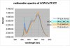
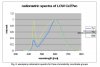
The below figure[1]shows a typical temperature vs. time curve for the reflow process:

The actual time and temperature requirements is dependent on the type of solder paste used. I use Kester Sn63/Pb37 (tin/lead) solder paster. The recommended reflow profile is below:

In general, solder pastes can be divided into two groups based on the composition of the solder. Most lead based solder pastes consist of an allow of tin (Sn) and lead (Pb). This composition has a melting point of 183°C.
Lead-free pastes usually consist of a tin (Sn), silver (Ag) and copper (Cu) alloy. Lead-free solder paste begins to melt around 217°C with a maximum reflow temperature of 240°C. Current Restriction of Hazardous Substances (RoHS) regulations require consumer electronics to contain lead-free solder (some exceptions apply).
One of the first questions that one may ask when considering the stages of the reflow process is how to go about implementing it. The simplest approach is to apply heat if the temperature is below the set point and turn off heating if the temperature is above the set point. This method of control is known as OFF-ON control or more simply as &#8216;Bang-Bang Control&#8216;. The problem with an OFF-ON control scheme is the temperature tends to over and undershoot the set point. This happens because the action-reaction of the reflow oven is not fast enough to regulate the temperature to maintain a constant set point. When the heating elements are turned off they do not immediately stop radiating heat. The internal temperature of the heating elements is higher than the temperature of the surrounding air so, thermal energy continues to transfer until they both are the same. When the temperature drops below the set point, the heating elements turn on but, it takes time for them to become hot enough to raise the temperature back to the set point. Thus, the temperature continues to drop until enough heat is applied to bring it back to the set point. A common way to deal with the issues of OFF-ON control is to use a PID routine which is the topic of our next discussion.


What is PID?

PID stands for &#8220;Proportional, Integral and Derivative.&#8221; Together, these three terms describe the basic elements of a PID controller. A PID controller is a type of control loop feedback system that calculates the difference between a measured input variable and a desired set point and attempts to minimize the error (how far are we away from set point) by adjusting the systems output.


What is Proportional Control?

The proportional term adds or subtracts output proportional to the current error value of the control system in order to drive the system back to the desired output (set point). The error value is given by how far the input (measured value) is away from the set point.
The proportional term is given by the following:
pTerm = Kp * error(t)
Where
Kp &#8211; A constant used to adjust the proportional response
error &#8211; Value given by subtracting the set point from the input (error = set point &#8211; input)
t &#8211; The time over which the input is sampled (sample time = 1 second for this explanation)
To summarize the proportional term:

  1. Error must exist in the system in order to have proportional drive.
  2. The system will try to correct the error by turning the heating elements &#8216;ON&#8217; or &#8216;OFF&#8217; in order to add or remove heat from the system.
  3. If the measured value is below the set point, heat will be added. If the measured value is above the set point, heat will be removed. If the measured value equals the set point, there is no error and thus, no proportional drive.
What is Integral Control?

A proportional only system would not be sufficient enough in our application to eliminate the error. Our system must be able to change its output according to the current error as well as past errors. The integral is proportional to both the magnitude (amount) of the error and the duration of the error. In other words, the integral is the sum of errors over time. This means the integral adds the amount of error as time passes and attempts to rapidly change the output to eliminate the error.
The integral term is given by the following:
iTerm = iTerm + (Ki * error)
Where
Ki &#8211; A constant used to adjust the integral response
error &#8211; Value given by subtracting the set point from the input (error = set point &#8211; input)
The integral component tracks accumulated error and attempts to accelerate the process towards the set point. This can cause the process to overshoot the set point if not kept in check. The integral component is kept in check in our application by clamping its output between a minimum and maximum value. The clamping routine is given by the following:
IF (iterm > outMax) THEN iTerm = outMax
IF (iTerm < outMin) THEN iTerm = outMin
Where
iTerm &#8211; Integral component
outMax &#8211; Maximum value the iterm can be
outMin &#8211; Minimum value the iTerm can be
To summarize the integral term:

  1. Error must exist in the system in order to have integral drive.
  2. The amount of error in the system is accumulated over time. Thus, a small error can become a large correction the longer error exists.
  3. The system is forced to correct the accumulated error.
  4. The effect from the integral component will cause the system to overshoot the set point as it attempts to reduce the accumulated error in the system if not limited.
What is Derivative Control?

The derivative term measures how quickly error changes with respect to time and affects the rate of change of the controller output. The rate of change is equivalent to measuring the slope of a line. The derivative term will attempt to reduce the magnitude of the overshoot that tends to be produced by the integral component.
The derivative term is given by the following:
dTerm = (currentTemperature &#8211; lastTemperature) * Kd
Where
currentTemperature &#8211; Current measured value
lastTemperature &#8211; Previous measured value
Kd &#8211; A constant used to adjust the derivative response
The derivative component must keep track of the previous measured value. This is accomplished by the following:
lastTemperature = currentTemperature
To summarize the derivative term:

  1. The system must be taking action. In other words, heat must be added or removed from the system over a period of time.
  2. The effect of the derivative component is based on how fast the system is heating up or cooling down within the sample period of once per second and is used to counter the overshoot produced by the integral component.
Output Drive&#8230;All Together Now!

Each of the PID components are calculated independently and added together to form the output drive. Take note that the dTerm is subtracted from the sum of the pTerm and iterm because the dTerm is derived from the measured input value(s). The output drive is what controls the process of determining how long to turn the system ON and OFF.
The output drive is given by the following:
Output = (pTerm + (iTerm &#8211; dTerm)))
Where
Output &#8211; Drive value for system control
pTerm &#8211; Proportional component
iTerm &#8211; Integral component
dTerm &#8211; Derivative component
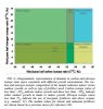
The output drive process is visualized in the below flowchart:

The above flowchart is a simplistic view of the temperature control process. The process begins by establishing a set point. The next step in the loop is to take a temperature reading. That temperature reading is used to calculate the error or how far we are away from the set point. Next, we calculate the Proportional, Integral and Derivative components and use those values to determine how much adjustment needs to be applied to regulate the system. In the case of our reflow oven, the amount of drive is determined by how long the heating elements are ON or OFF. This type of control can be considered a different take on the PID algorithm and is know as Time Proportional Control (TPC).
Time Proportional Control

Time Proportional Control, a form of Pulse Width Modulation (PWM), is a mathematical technique that allows a feedback controller to use an ON-OFF discrete actuator, such as a relay or Solid State Relay (SSR), as if it were a continuous actuator cable of generating control efforts anywhere between 0 and 100%. The concept of TPC is to turn the actuator ON and OFF for periods proportional to the desired control effort.
Our routine is given by:
timeOn = (tCycle * Output)/100
Where
timeOn &#8211; Value indicating how long power will be applied to the heating elements
tCycle &#8211; Time span for process
Output &#8211; Calculated value from the PID routine
The routine needs to keep track of how much time has elapsed in order to stay within the set process time span. This is accomplished by the following:
Tvar = Tvar + 1
IF (Tvar >= outMax) THEN Tvar = outMin
Where
Tvar &#8211; Variable used to track how much time has elapsed
outMax &#8211; Maximum value Tvar can be
outMin &#8211; Minimum value Tvar can be
The minimum and maximum time span for our application is 0 and 10 seconds, respectively. The above routine ensures the process time span does not go below or exceed the set time span.


http://hobbybotics.com/projects/hobbybotics-reflow-controller-v8-03/
 

stardustsailor

Well-Known Member
Something really interesting ......


Stable Isotope Ratios of Marijuana. I. Carbon
and Nitrogen Stable Isotopes Describe
Growth Conditions.....


mj analysing.JPG......


http://ehleringer.net/Jim/Publications/396.pdf


"........JOURNAL OF FORENSIC SCIENCES...."

They examine the isotopes of N & C and they can find out ,what nutes you've used or if you had the lady on shade ........
...
Much trouble for no reason ,really ....


....................................................
And for our US brothers ....Some " hommie -stats " ,there :


states state.jpg.....
Seems that NY & Seattle have the most 'hardcore' indoor growers ..
While in Arizona ,a "grow-tent" is still something unknown to them .....
"Guerrillas " most of them ,there ...


Tracing retail cannabis in the United States:
Geographic origin and cultivation patterns
http://ehleringer.net/Jim/Publications/409.pdf


Stable isotope models to predict geographic origin and cultivation
conditions of marijuana
http://ehleringer.net/Jim/Publications/410.pdf


More about :
http://ehleringer.net/Jim/Publications/403.pdf


......For God's shake ...WTF I'm sittin' n' readin' in the middle of the night ...
 

Fonzarelli

Active Member
Would a glass blowing annealing oven work for reflow? I've wondered this for quite some time. It has a programmable Fuji step controller on it so I could program every step to the minute.

Is the cool down timing crucial? The only drawback is how slow it would cool due to the firebrick and insulation in the oven so not sure if that's good or bad for reflowing.

I could do 50 2ft x 2ft LED panels with the oven I have. Lol
 

stardustsailor

Well-Known Member
Would a glass blowing annealing oven work for reflow? I've wondered this for quite some time. It has a programmable Fuji step controller on it so I could program every step to the minute.

Is the cool down timing crucial? The only drawback is how slow it would cool due to the firebrick and insulation in the oven so not sure if that's good or bad for reflowing.

I could do 50 2ft x 2ft LED panels with the oven I have. Lol
Do not think so ,really ,Fonz ....

Usually reflow ovens have a max working temp of ~300 °C .
And also do have really presice time-temp controllers ,Like i.e. with ' PID architecture ' ..

Still ,personally ,I 've managed to reflow (and rework) metal core & FR4 pcbs ,with quite decent results ,using either kitchen's hot plate or
a camping gas stove ....Reflow soldering ,once it's "principles" are understood and after couple of tries ,actually is a piece of cake ...
Even if done "manually " ...
It's rather a delicate procedure ,than difficult ....
And takes a bit of training ....

Dunno ....
Maybe it is doable,with that kind of oven,also ....

place an old pcb from an old electronic device ..I.e an old pc motherboard ...

Follow / set a "standard " solder profile (each solder alloy has it's own )..
And see what happens .....

If soldered components start to "reflow " smoothly ....

Probably the oven can be used for reflowing ....

Cooling has to be gradual and not rapid ...
Otherwise pcb might deform from 'flat ' ,ceramic cases of leds might crack ,led die/chip contacts might detach ,etc ....
 

stardustsailor

Well-Known Member
One out of three ,showed balls ( ' male ' primordia/preflowers ) and was removed...
-Seeds were all regular,not feminised -

Rest two will ' finish ' this day and one more -tomorrow-in veg and then leds will be changed into 13/11 cycle for a week .

P5216587.JPGP5216585.JPGP5216584.JPG
......
 

Fonzarelli

Active Member
Do not think so ,really ,Fonz ....

Usually reflow ovens have a max working temp of ~300 °C .
And also do have really presice time-temp controllers ,Like i.e. with ' PID architecture ' ..

Still ,personally ,I 've managed to reflow (and rework) metal core & FR4 pcbs ,with quite decent results ,using either kitchen's hot plate or
a camping gas stove ....Reflow soldering ,once it's "principles" are understood and after couple of tries ,actually is a piece of cake ...
Even if done "manually " ...
It's rather a delicate procedure ,than difficult ....
And takes a bit of training ....

Dunno ....
Maybe it is doable,with that kind of oven,also ....

place an old pcb from an old electronic device ..I.e an old pc motherboard ...

Follow / set a "standard " solder profile (each solder alloy has it's own )..
And see what happens .....

If soldered components start to "reflow " smoothly ....

Probably the oven can be used for reflowing ....

Cooling has to be gradual and not rapid ...
Otherwise pcb might deform from 'flat ' ,ceramic cases of leds might crack ,led die/chip contacts might detach ,etc ....
The annealer has a Digital Fuji step controller capable of running an 8 step program with hold times in 1 minute increments. The only thing I couldn't do is cool down fast so as long as a slow cool down is ok then it seems like it would work great.

I can ramp up to over 1200F hold for a minute, bring down to 900 hold for a minute and cool to 72 over a period of minutes or hours.
 
Top