Mau5Capades: builds & grow journal

robincnn

Well-Known Member
It's a great HS but passive cooling of CXB3590 @1.4A cost me less than $15 with extruded profiles...
I second this. As someone who runs passive cooling @1.05A I simply don't need all that much aluminum. at the same time however I would love a product like this as opposed to basic heatsinksusa profiles, it would just have to compete with less than $13 per cob. a scaled down version for $15-20 each would be pretty sweet.
The one i have is for $20 a piece already. Rest all is shipping, paste, template, screws, hanger. I shared the numbers already.
Good for 1.75A and may be even 2.1A.
I second you both. $15 @1.4A and $13 @1.05A seems reasonable for passive heatsinks without any pre-tapped holes.
 

Greengenes707

Well-Known Member
Also depends of what someone defines as "cooling". Tc=80c or Tc=50c. Can take up to twice as much aluminum, to go from 80c to 50c...yet both are considered being kept cool.
To me(and the cob manufacturers) Tc is what matters...not sink temp.

PLC will have sinks soon. You have seen the cooliance's in the protos. I've tested every profile from 100mm to to 160mm...160 is actually being done as we speak. And some mechatronic. Will post the final results soon once it's all together.
 

Fastslappy

Well-Known Member
$15 @1.4A and $13 @1.05A seems reasonable for passive heatsinks without any pre-tapped holes.
shipping is the wild card on any sink
but in my research i didn't come close to that $ figure , the Heatsink USA sinks just don't appeal to me for the costs & weight
3590 @1400 is where i'm at , i'm using cpu coolers atm ,
i just don't want the weight of Heatsink USA rigs are at
is the why for cpu coolers for me , it's Just a preference on my part Not Dissing anybody's builds mind u
 

robincnn

Well-Known Member
Last edited:

Greengenes707

Well-Known Member
cpl12070 profile's are great for ~50w.
How is this looking
3590CD 71.3V 0.75A = 53.47W may be 24W heat
Ths 45C, Ta 20C, Ts 46C-47C

No air movement.
About 1C/W at 25 Watts and about 0.80C/W at 45-50 Watts. Even less with air movement.
Ths position directly opposite side of COB at base plate. measuring tools
https://www.rollitup.org/t/new-heatsink-concept.898414/page-3#post-12308312
https://www.rollitup.org/t/thermometers-thermocouples-and-thermal-readings.896353/#post-12256364
All good. When you have both...who cares.
But on it's own...I want Tc, not Tsink. Some profiles are consistent, and some will show variance up or down from Tc. These differences in the sinks conductance characteristics(shape, material, source size/number) is taken away by going straight to the Tc, where it is meant to be measured. When the way to do it is easy, I make sure to do it. Manufacturer's warranties will ask about heat management and being able to show them everything is beyond within spec in the way that the manufacturer states it is to be measured is how it needs to be. It's not hard, and even the simplest minded of DIY have the ability to check Tc correctly and cheaply if that is their goal. Thermal resistance is a damn good tool to actually have an idea of what is going on with the Tc and instead just going on a "this much will work" kind of recommendation. The definition of what is "will work" is very ambiguous.

Then there is passive vs active being measured. Active not reaching an equilibrium so much and the delta between Tc and Tsink can be greater.
 

robincnn

Well-Known Member
cpl12070 profile's are great for ~50w.
I agree.
I have similar to 14070 so they can handle even more like 1750ma
Also extra cooling from metal if heatsink connected to frame and airflow.
I took Ths and Tc both to get an idea about thermal paste resistance. Some of my data indicates Ths increasing and Tc decreasing next day as Thermal paste sets. May not not an issue with thermal pads.
Looking forward to seeing your data.:weed:
 

AquariusPanta

Well-Known Member
I believe someone stated awhile back (maybe SDS) that thermal pads don't work as effectively as actual thermal grease for our lighting applications. Of course anything is set to change over time, especially when it's technology related. I'm a sucker for using the cheaper, proven route, which is thermal grease, although I'd like to try out a few thermal pads at some point to see whether they're worth the extra coin or if spending ~30 seconds spreading and applying grease is the better method.
 

BobCajun

Well-Known Member
If anyone wants to make PWM dimmers you can do it with these Arduino microcontrollers. Most of the tutorials specify Arduino Diecimila or Duemilanove but they're old models I guess and a little hard to find. Now they have Uno models based on the same ATmega328 microcontroller. Pretty sure you could do the same things with them as the earlier ones. Maybe you could find those particular models, I didn't look very hard. With them you can set various frequencies and duty cycles. BTW, although a 33% duty ratio produces best results, 50% is not far behind. I'll let people figure out how to get 100-400 microsecond pulses at 33-50% duty cycle themselves.

The Arduino PWM normally puts out 5v, so you'll have to use one of the tutorials on converting the 5v to 10v.

Here's a general introductory video.

 
Last edited:

BobCajun

Well-Known Member
https://www.google.com/patents/WO2010085513A1?cl=en

Pretty interesting article on pulse lighting seeds with UV to increase yeild.
I wouldn't mess around with UVC just for a 5-10% yield increase, but interesting patent nonetheless. Now about the Arduinos, this forum post has some useful info. Looks like it might burn the chip out if you put a 10v signal through it instead of 5, so I guess you'd have be careful about that.
"1. Arduino Nano $25, ebay
2. 6 channels digital potentiometer (10K, 255steps, 0-5V) buy more than 3, you will need it as it can easily be fried.
3. Low Power Op-Amp, you can buy some high power one as well, but it doesn't matter
4. 500mA transistor, I used it, but it got hot real hot real quick when I put more than 100mA on it, so I would recommend higher power ones.
5. A whole bunch of equal resistors (10k or 100k)

That's all there is to the 0-10V controller. Here are the basic steps.

1. The digital potentiometer is driven by the Arduino via SPI (3 wires connection to the Arduino), you can look at the SPI potentiometer example on the Arduino program. The pot has 6 channels and each channels has 255 steps. 0 = 0V and 255 = 5V when powered by a 5V source. It is VERY VERY VERY important that you power this chip with only 5V or you will fried it! Trust me, I fried 2 or them. Luckily I ordered 5.
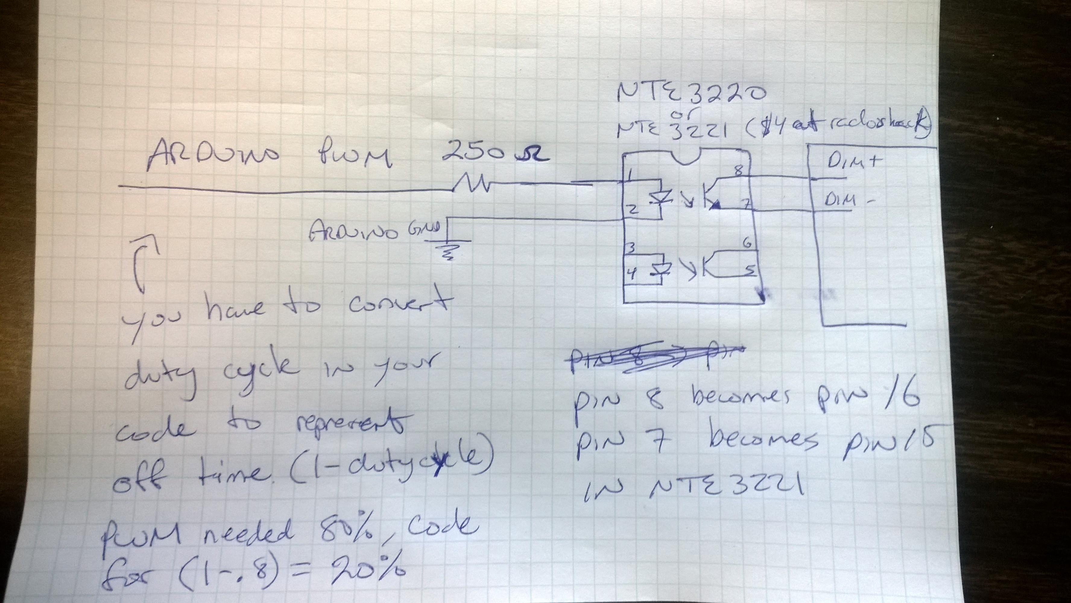
2. The digital pot output to the op-amp is driven by a 12V source. The opamp multiply the voltages to 10V using 2 identical resistor to the "-" of the opamp. I will post schematic tomorrow. DO NOT POWERED anything off of this 10V, it is very little current as it is only signal. You may *caution* get by with powering the ELN----D with this, but monitor how hot the opamp get and measure the actual voltage. To be safe, I would suggest going to step 3.
3. The output from the opamp go to the "Base" of the transistor (would recommend getting the higher power one), the return signal to the opamp from the resistor is the emitter with a resistor.

Again, electrical diagram to follow tomorrow. This will give you a clean linear 0-10V signal and whatever current you can run through the transistor. In addition, you only use 2pwm (pin 10,11) and 1 clock (pin 13) from the arduino but you get 6 channels out." source
[/QUOTE)
 

Mr. Candiano

Active Member
I wouldn't mess around with UVC just for a 5-10% yield increase, but interesting patent nonetheless. Now about the Arduinos, this forum post has some useful info. Looks like it might burn the chip out if you put a 10v signal through it instead of 5, so I guess you'd have be careful about that.
I like the concept of pulse lighting but thought the same. On off repeated I'm sure would reduce the life of the cob.
 

Fastslappy

Well-Known Member
Also, cobs seem to go out slowly, as in when the power off is hit, the cobs take a little time to go out completely, so it would be difficult to have actual lights out in such short bursts.
Laser is the only hope :fire: here

Or spin a disk on yer cobs
 

BobCajun

Well-Known Member
I like the concept of pulse lighting but thought the same. On off repeated I'm sure would reduce the life of the cob.
On/off cycles have no effect on the life of LEDs, to my knowledge. That's fluorescent and HID. And there's no warmup or cooldown time. You can flash Meanwell PWM dimmers without any problem. Here's another forum post I found which may be helpful in using Arduinos with meanwell drivers. This looks like the simplest and cheapest way to couple the Arduino to a 0-10v LED dimmer circuit.

I looked at the data sheet for the HLG- 6 0H-C. The Dim+ brings its own pull-up 10V source with pull-up resistor (as you can just use resistors from DIM+ to DIM- to control dimming. You can also, as you stated, introduce a PWM signal of 10V to those pins. This MeanWell design allows you to do a mix of both, using the HLG's pullup resistors and 10V supply to provide it's own PWM signal. You just have to use an optocoupler (NTE 3220 or 3221) to get the 5V PWM signal from the Arduino into the MeanWell at 10V ($4 a Radioshack, plus a 250 ohm resistor). Optocoupler will prevent you from having to worry about the grounding schemes between the MeanWell and the Arduino.

The only thing is that you have to invert the logic in your PWM code. For example, if you want the light on at 75% full strength, code the PWM in the arduiono at 25%. Light at 100% strength, equals PWM at 0%, etc. Light strength = (1-PWM_arduino_code). You could introduce an inverter IC at the PWM output to keep the 1:1 light:PWM relationship, but when designing, an easy fix via software is always better than introducing more hardware. source
Image from the post;

 
Last edited:

BobCajun

Well-Known Member
I made some THCA yesterday. Not bad stuff. I posted about it on the concentrates and extracts forum but apparently not many people read that forum, probably because it's way down the list. Here's the thread.
 

alesh

Well-Known Member
I like the concept of pulse lighting but thought the same. On off repeated I'm sure would reduce the life of the cob.
I don't think so.

Also, cobs seem to go out slowly, as in when the power off is hit, the cobs take a little time to go out completely, so it would be difficult to have actual lights out in such short bursts.
That's because of drivers not COBs. There's a pretty large capacitor on the output of most drivers which causes delay when powering on and discharges a few seconds after the power is off. LEDs themselves are as close to instantaneous as could be.
 

BobCajun

Well-Known Member
About the pulse thing, it's going to make the light look dim, like a normal dimmer would. Maybe if you used twice as much wattage per area it would still look normal, if it was a 50% duty cycle. Would it increase yield? Probably, yeah. You just wouldn't save any power that way. Still, if you could get 50% more yield with the same wattage that would certainly be an advantage.
 

ttystikk

Well-Known Member
About the pulse thing, it's going to make the light look dim, like a normal dimmer would. Maybe if you used twice as much wattage per area it would still look normal, if it was a 50% duty cycle. Would it increase yield? Probably, yeah. You just wouldn't save any power that way. Still, if you could get 50% more yield with the same wattage that would certainly be an advantage.
If it works, it's a wiring or even a software upgrade. I think it would be applicable to nearly any lighting design that could handle the pulse rate.
 

Abiqua

Well-Known Member
I believe someone stated awhile back (maybe SDS) that thermal pads don't work as effectively as actual thermal grease for our lighting applications. Of course anything is set to change over time, especially when it's technology related. I'm a sucker for using the cheaper, proven route, which is thermal grease, although I'd like to try out a few thermal pads at some point to see whether they're worth the extra coin or if spending ~30 seconds spreading and applying grease is the better method.
he suggested not to use a graphite pad on a Vero when mounted on aluminnum....Corrosion will set in more quickly or along those lines....He actually didn't go off on Cree kind of ;) and mentioned that the Ceramic base would in theory work better with graphite pads on aluminum...Again I am paraphrasing very shittily and there might me more context....

I know I don't have the big fancy data sets that y'all are working on...

but I don't own or build lights for money...Just to facilitate my growing urges :)....so the Datasets are slow to never happening in my case, simply because this ain't my job :)

That said....I have been using Graftech up to 25 watts Pd on variety of Diodes....Vero's the longest though @ 4-5+ months now @ 23 watt Pd rough estimate, currently in the flower tent too....

Few others are on the radar, especially the PLC ones, but I find no reason they are not functional. Anecdotally only unfortunately. :peace:
 
Top